
Pneumatically inflatable air bladder devices contained entirely within shoe sole or configured as shoe inserts

a technology of pneumatic cushioning and air bladder, which is applied in the field of shoes, can solve the problems of complex manufacturing of integrating pneumatic cushioning devices within the shoe sole or as shoe inserts

Inactive Publication Date: 2015-10-29
DOYLE HAROLD S
View PDF14 Cites 36 Cited by
  • Summary
  • Abstract
  • Description
  • Claims
  • Application Information

AI Technical Summary

Benefits of technology

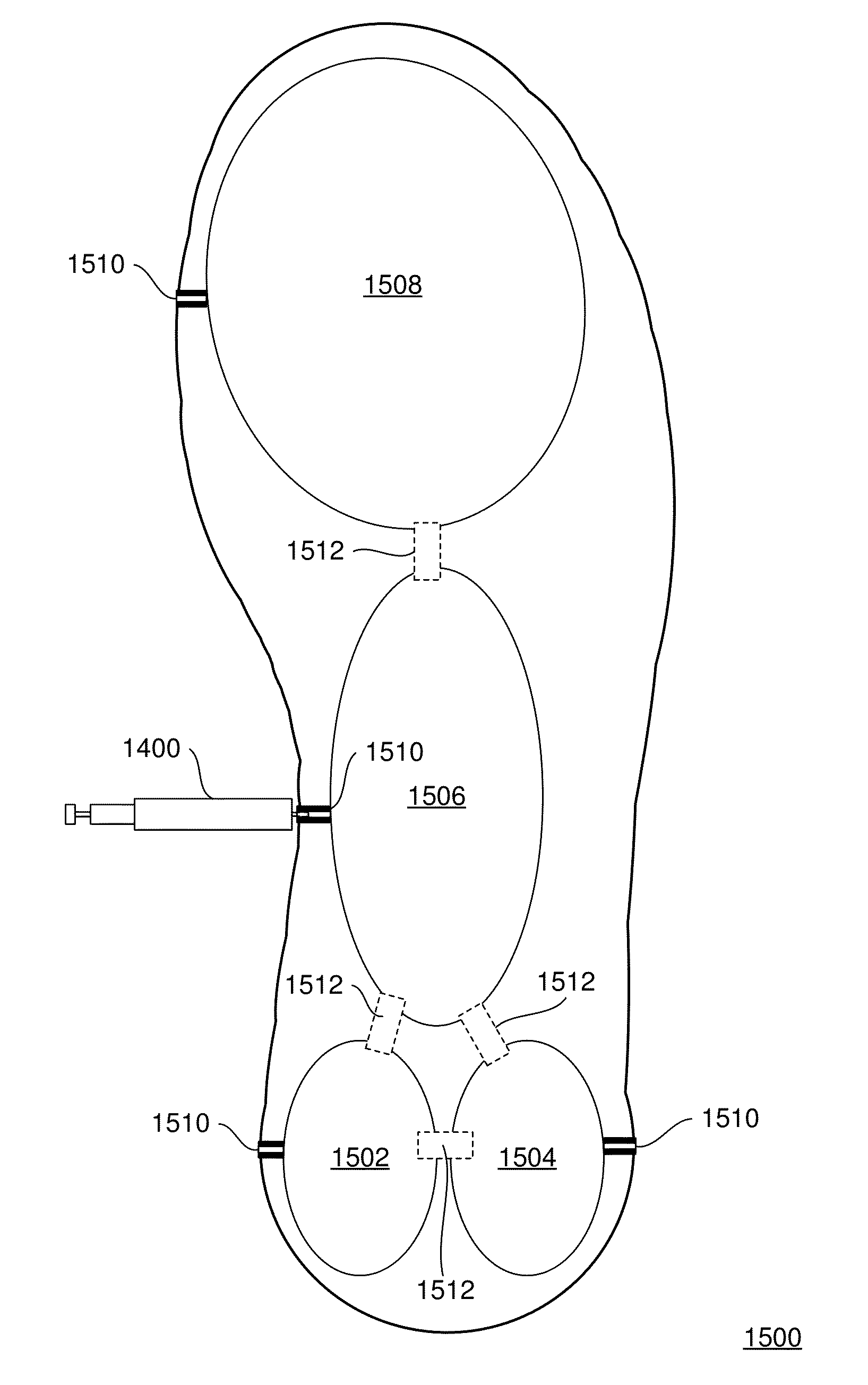
The present invention provides an improved pneumatic cushioning system for shoes by providing a plastic layer forming air bladders, a cloth layer covering a top surface of the plastic layer, a rubber layer covering a toe portion of a bottom surface of the plastic layer, and a C-shaped indentation on the plastic layer forming an arch region air bladder. The rubber layer including cutting lines for sizing for regular or wide foot sizes and a lower thicker line defining a do not cut below region. The cloth layer including cutting lines for the other of regular or wide foot sizes. The air bladders are pre-filled with air during manufacturing or filled with air by a user. A self-sealing valve can be disposed on the air bladders regions to allow air to enter the regions while maintaining air pressure. The valve can be accessed external to the shoe for inflation and deflation via an air pump needle or an integrated pump and release valve device. The device can be integrated into a sole of a shoe or a shoe insert with the valve. The valve can be movable from a first position to pump air and from a second position to allow air to escape. The patent describes various embodiments and modifications of this invention.

Problems solved by technology

However, many of such designs still suffer from various problems relating to air bladder placement, and inflation thereof, and complex manufacturing for integrating the inflation devices within the shoes themselves.

Method used


Image

  • Pneumatically inflatable air bladder devices contained entirely within shoe sole or configured as shoe inserts
  • Pneumatically inflatable air bladder devices contained entirely within shoe sole or configured as shoe inserts
  • Pneumatically inflatable air bladder devices contained entirely within shoe sole or configured as shoe inserts

Examples


Embodiment Construction

[0039]Referring now to the drawings, wherein like reference numerals designate identical or corresponding parts throughout the several views, and more particularly to FIG. 1 thereof, there is illustrated

[0040]The present invention is directed to a shoe with a pneumatic inflating device disposed therein. The general schematic of the shoe inflating arrangement is shown in FIG. 1 and includes three bladder sets. However, it will be apparent that the arrangement is adaptable to any plurality of bladder sets. The arrangement includes a pump 12 with an inlet 14 and an outlet 16. Outlet 16 is connected to a flow switching device 18 at a flow switching input 20. Flow switching device 18 operates as a selective valve which allows air flow into at least two outlets, the preferred embodiment having a first outlet 22, a second outlet 24, and a third outlet 26. Each outlet 22, 24, and 26 is connected to a corresponding conduit 28, 30, and 32. Each conduit 28, 30, and 32 is associated with corres...


PUM


Abstract

A pneumatically cushioned shoe or shoe insert device including a plastic layer forming air bladders; a cloth layer covering a top surface of the plastic layer; a rubber layer covering a toe portion of a bottom surface of the plastic layer; a C shaped indentation on the plastic layer forming an arch region air bladder; and circle or oval shaped indentations forming interconnected air bladder regions having respective air bladders and including an inner heel, outer heel, and metatarsal air bladder regions. The rubber layer including cutting lines for sizing for regular or wide foot sizes and a lower thicker line defining a do not cut below region. The cloth layer including cutting lines for sizing for the other of regular or wide foot sizes. The air bladders pre-filled with air during manufacturing or filled with air by a user.

Description

CROSS REFERENCE TO RELATED DOCUMENTS[0001]The present invention claims benefit of priority to U.S. Provisional Patent Application No. 61 / 984,184 filed Apr. 25, 2014, and is a continuation in part (CIP) of U.S. patent application Ser. No. 13 / 237,566 filed Sep. 20, 2011, which claims benefit of priority to U.S. Provisional Patent Application No. 61 / 386,274 filed Sep. 24, 2010, and is related to commonly-assigned U.S. Patent Application No. 12 / 884,132, and U.S. Pat. Nos. 5,222,312; 6,305,102; and 6,725,573 of Harold S. DOYLE, the entire disclosures of all of which are hereby incorporated by reference herein.BACKGROUND OF THE INVENTION[0002]1. Field of the Invention[0003]The present invention generally relates to shoes, and, more particularly, to pneumatic cushioning therein.[0004]2. Discussion of the Background[0005]There is a variety of prior art shoes including a variety of inflation devices disposed at different locations therein. However, many of such designs still suffer from vari...

Claims


Application Information

Patent Timeline
Patent Type & Authority Applications(United States)
IPC IPC(8): A43B13/20A43B7/24A43B17/03
CPCA43B13/203A43B7/24A43B17/035
Inventor DOYLE, HAROLD S.
Owner DOYLE HAROLD S
Learn More