Eureka AIR delivers breakthrough ideas for toughest innovation challenges, trusted by R&D personnel around the world.

Brush Assembly for an Electric Motor

a technology for electric motors and cage brushes, applied in current collectors, electrical devices, dynamo-electric machines, etc., can solve problems such as abnormal noise, and achieve the effects of eliminating abnormal noise, reducing the vibration of brushes, and improving stability

Active Publication Date: 2015-10-22
JOHNSON ELECTRIC SA
View PDF3 Cites 2 Cited by
  • Summary
  • Abstract
  • Description
  • Claims
  • Application Information

AI Technical Summary

Benefits of technology

The patent describes a brush assembly for an electric motor that reduces vibration and abnormal noises, making it more stable and efficient. This is achieved by configuring the stop plates of the hooks with different angles, allowing the brush to abut against one inner surface of the brush cage. The motor using this brush assembly has improved stability and reduces abnormal noises during slow-down of the motor after power off.

Problems solved by technology

As a result, during operation of the motor, vibration of the brush 2 can easily occur which may cause abnormal noises.

Method used


Image

  • Brush Assembly for an Electric Motor
  • Brush Assembly for an Electric Motor
  • Brush Assembly for an Electric Motor

Examples


Embodiment Construction

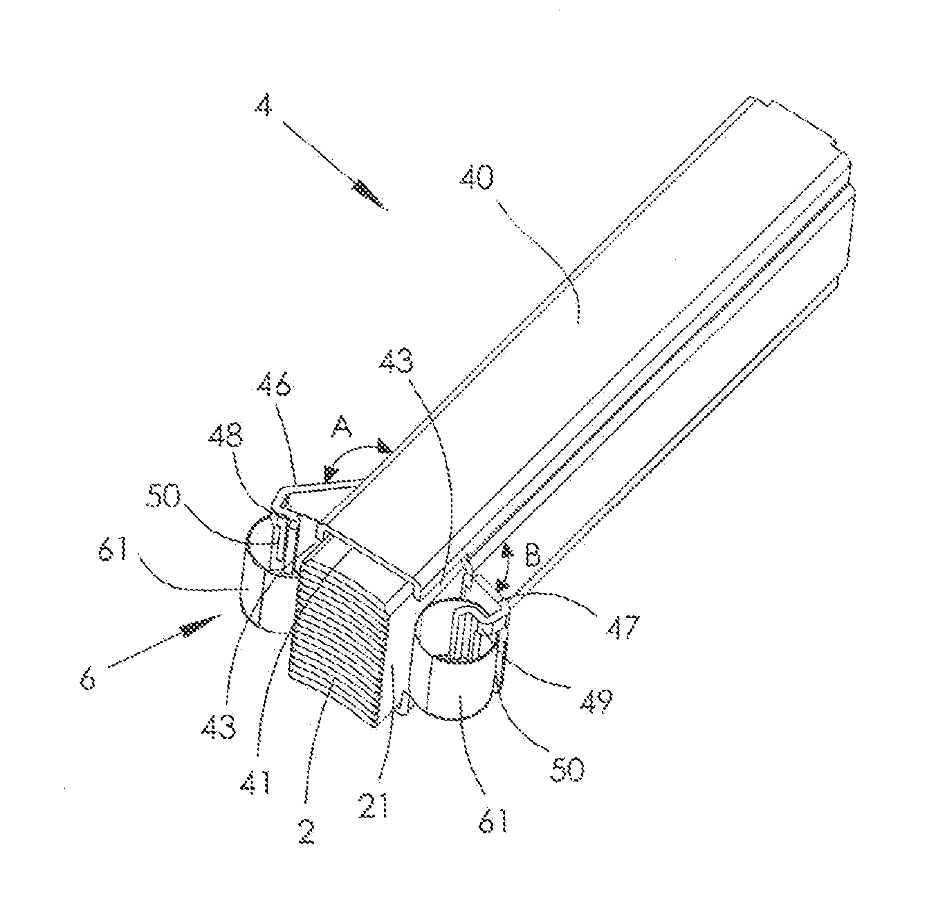
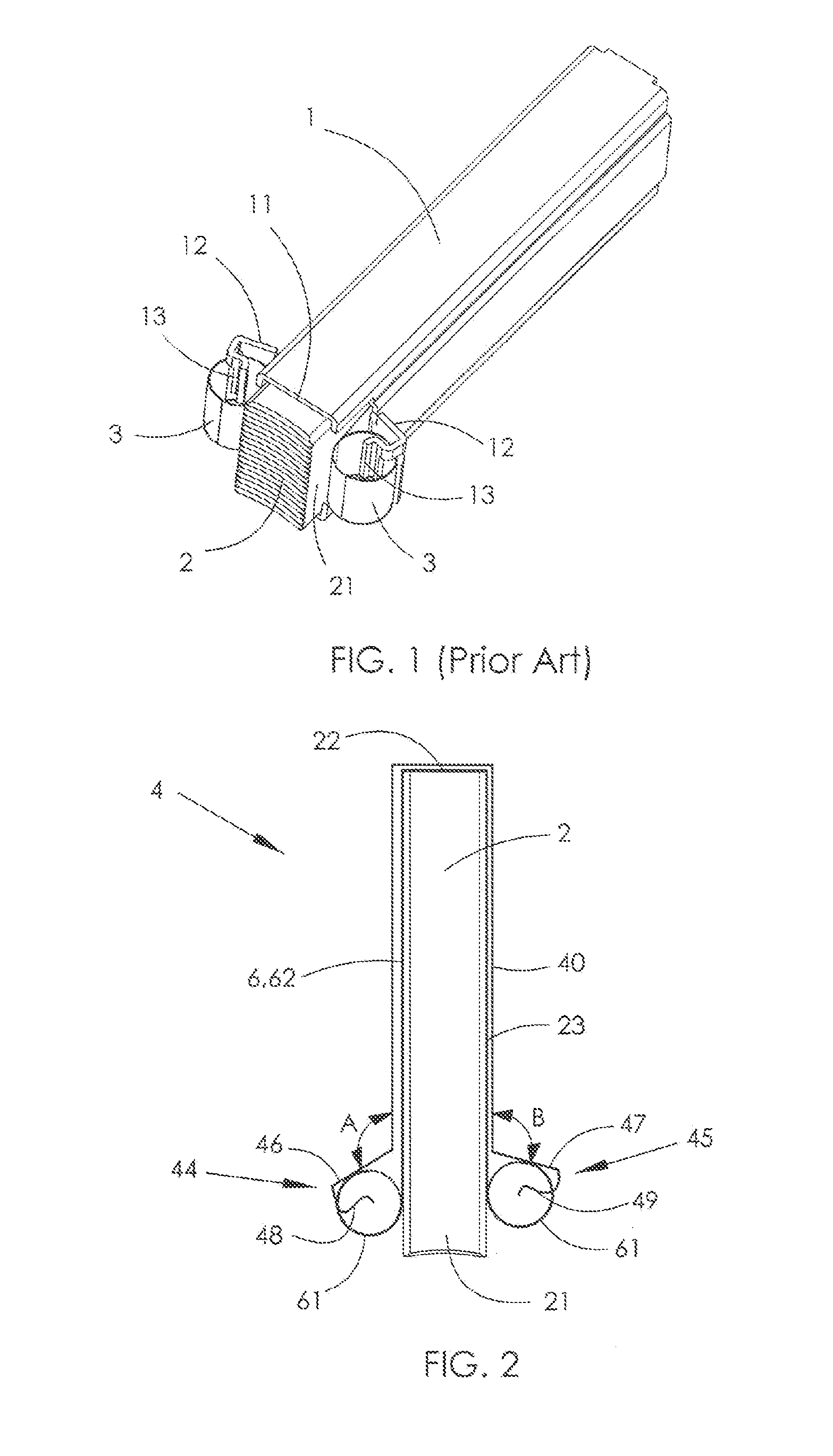
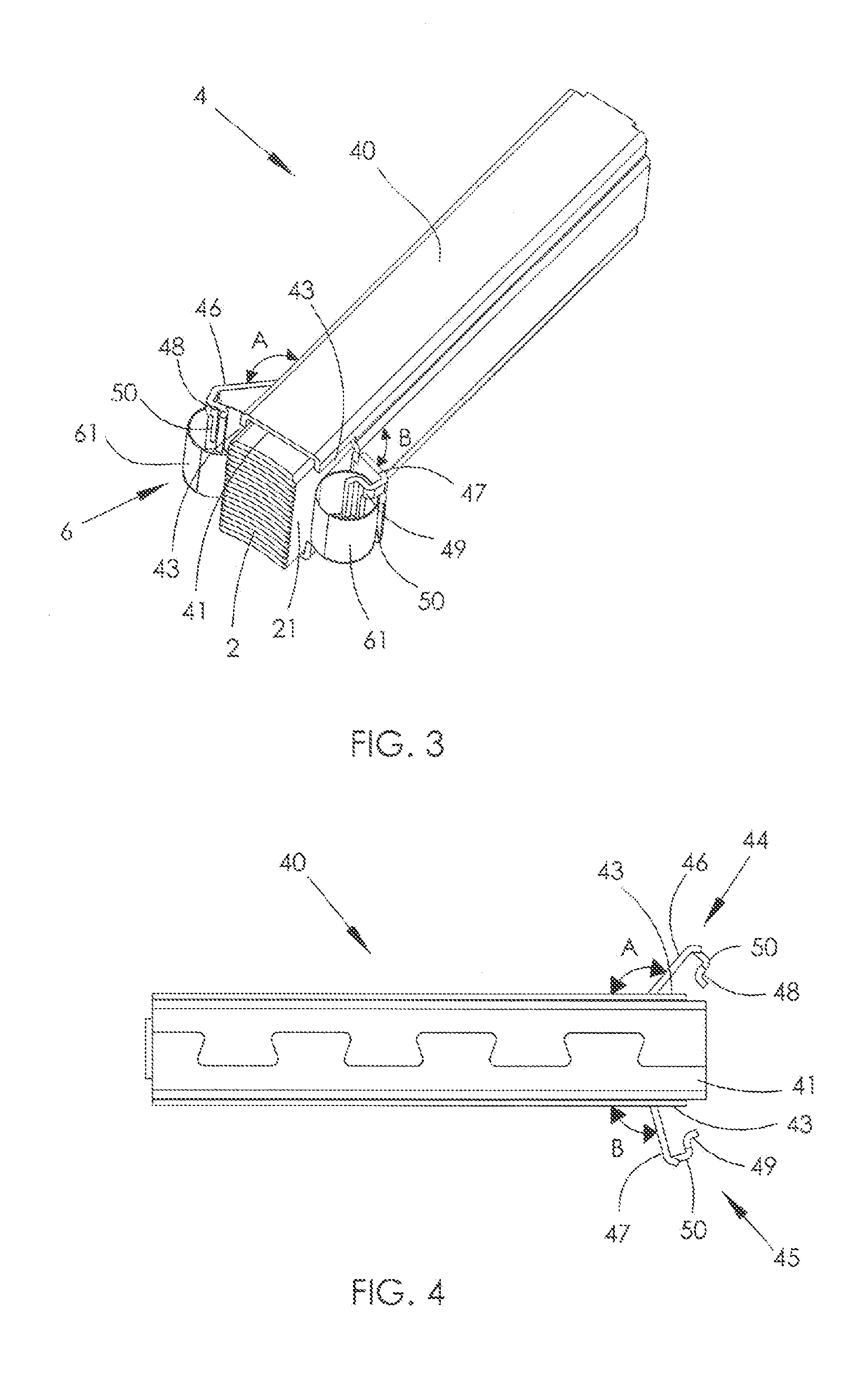
[0021]FIGS. 2 and 3 illustrate a brush assembly 4 for an electric motor, in according with the preferred embodiment of the present invention. FIG. 2 is a diagrammatic representation used to illustrate the concept while FIG. 3 is a perspective view of the complete brush assembly. The brush assembly 4 includes a brush 2, a brush cage 40, and a spring 6. In the present embodiment, the brush cage 40 is hollow and elongated in shape. The brush 2 includes a contact end 21 and a second end 22 remote from the contact end 21. FIG. 4 illustrates the underside of the brush cage of FIG. 3.

[0022]The spring 6 is a constant-force spring, including two coil portions 61 and a U-shaped connecting portion 62 interconnecting the coil portions 61. The connecting portion 62 of the spring 6 abuts against the second end 22 of the brush 2, and the connecting portion 62 of the spring and the brush 2 are together received in the brush cage 40, as shown in FIG. 2.

[0023]The brush cage 40 is formed with a hook a...


PUM


Abstract

A brush assembly has a brush, a brush cage, and a spring. The spring is a constant force spring having two coil portions and a connecting portion. The connecting portion the brush are together received in the brush cage. The brush has a contact end arranged to make sliding contact with a commutator and a second end remote from the contact end against which the spring applies its force, to urge the brush out of the brush cage. A hook is formed at each of two opposite sides of the brush cage, at a first end portion of the brush cage adjacent the contact end of the brush. The coil portions respectively engage the hooks. The hooks extend at different angles to a corresponding outer surface of the brush cage.

Description

CROSS REFERENCE TO RELATED APPLICATIONS[0001]This non-provisional patent application claims priority under 35 U.S.C. §119(a) from Patent Application No. 201410159001.0 filed in The People's Republic of China on Apr. 18, 2014, the entire contents of which are hereby incorporated by reference.FIELD OF THE INVENTION[0002]This invention relates to a cage brush assembly for an electric motor and, in particular to a brush assembly for use with a constant force spring.BACKGROUND OF THE INVENTION[0003]Motors are an electromagnetic device for electric energy conversion according to the law of electromagnetic induction, which mainly include direct current motors and alternating current motors. The direct current motors or universal brush motors require a brush assembly. The brush assembly includes a brush and a brush cage. The brush is mounted in the brush cage and is biased by a spring. The brush contacts a commutator to transfer the electrical current from the brush to the commutator.[0004]...

Claims


Application Information

Patent Timeline
Patent Type & Authority Applications(United States)
IPC IPC(8): H01R39/38
CPCH01R39/381
Inventor WEI, HONG MINDENG, YINLIU, BINXING, HUI JUAN
Owner JOHNSON ELECTRIC SA
Why Eureka
Eureka Blog
Learn More