
Sheet feeding device and image forming apparatus

Inactive Publication Date: 2015-10-22
CANON KK
View PDF6 Cites 0 Cited by
  • Summary
  • Abstract
  • Description
  • Claims
  • Application Information

AI Technical Summary

Benefits of technology

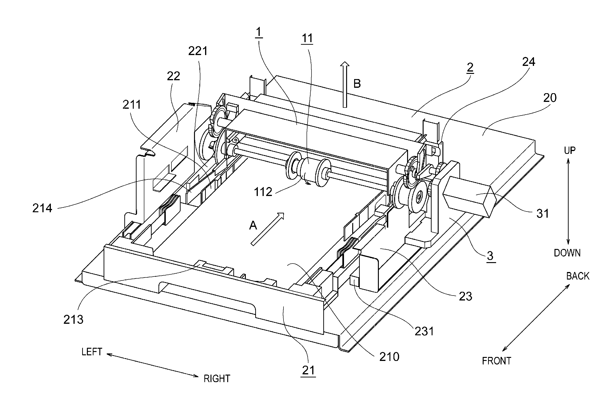
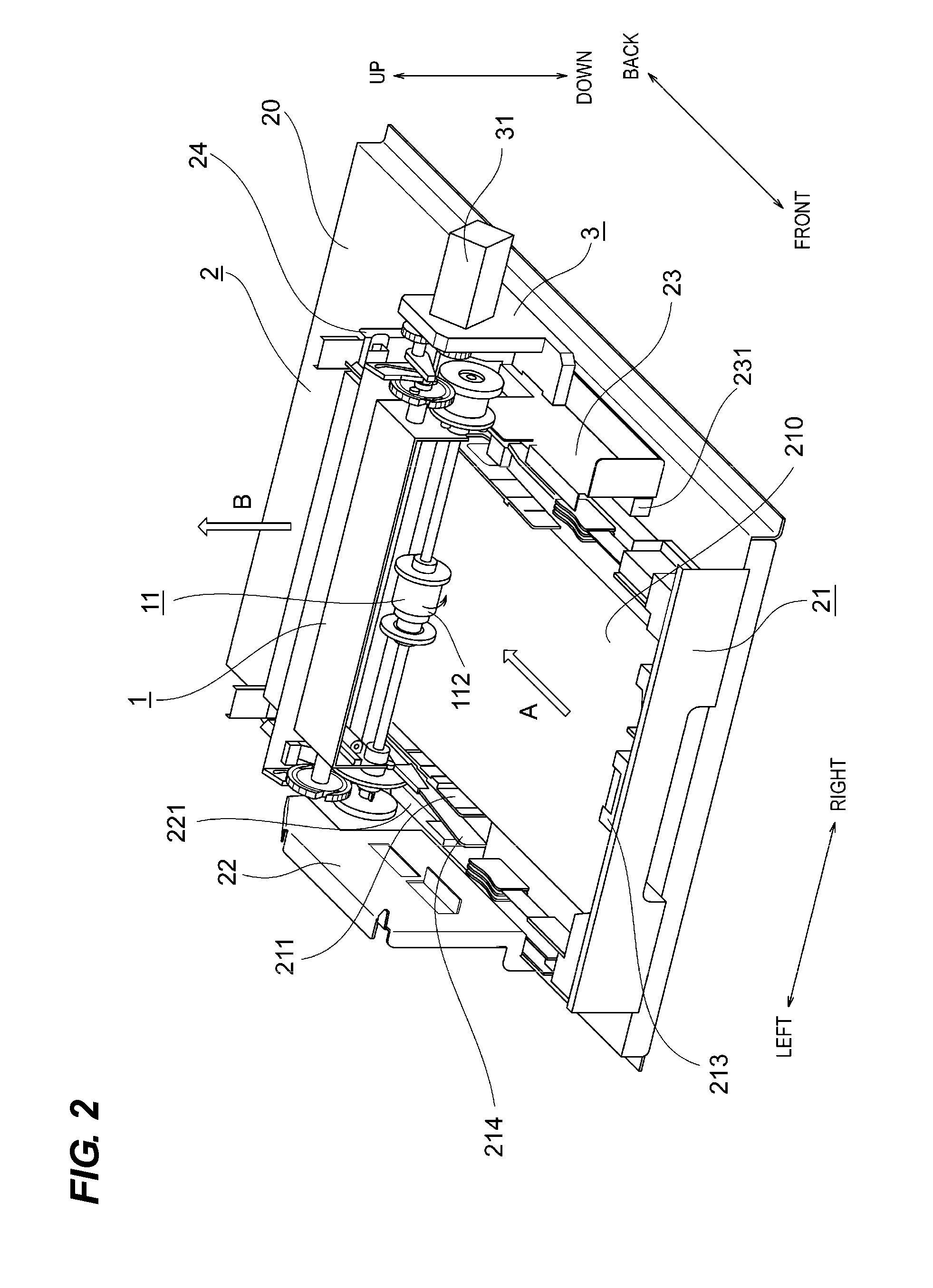
The invention provides a sheet feeding device that can be installed in a smaller space than previous devices. The device holds the sheet at the tip and then returns it to a position closer to the feeding portion. This reduces the protrusion in the sheet feeding direction and allows for a smaller device size and installation space.

Problems solved by technology

Since the protrusion portion directly influences the installation area of the device, this protrusion portion disturbs a design of the device which is attachable to a small space due to the small size thereof.

Method used


Image

  • Sheet feeding device and image forming apparatus
  • Sheet feeding device and image forming apparatus
  • Sheet feeding device and image forming apparatus

Examples


first embodiment

Overall Configuration of Image Forming Apparatus

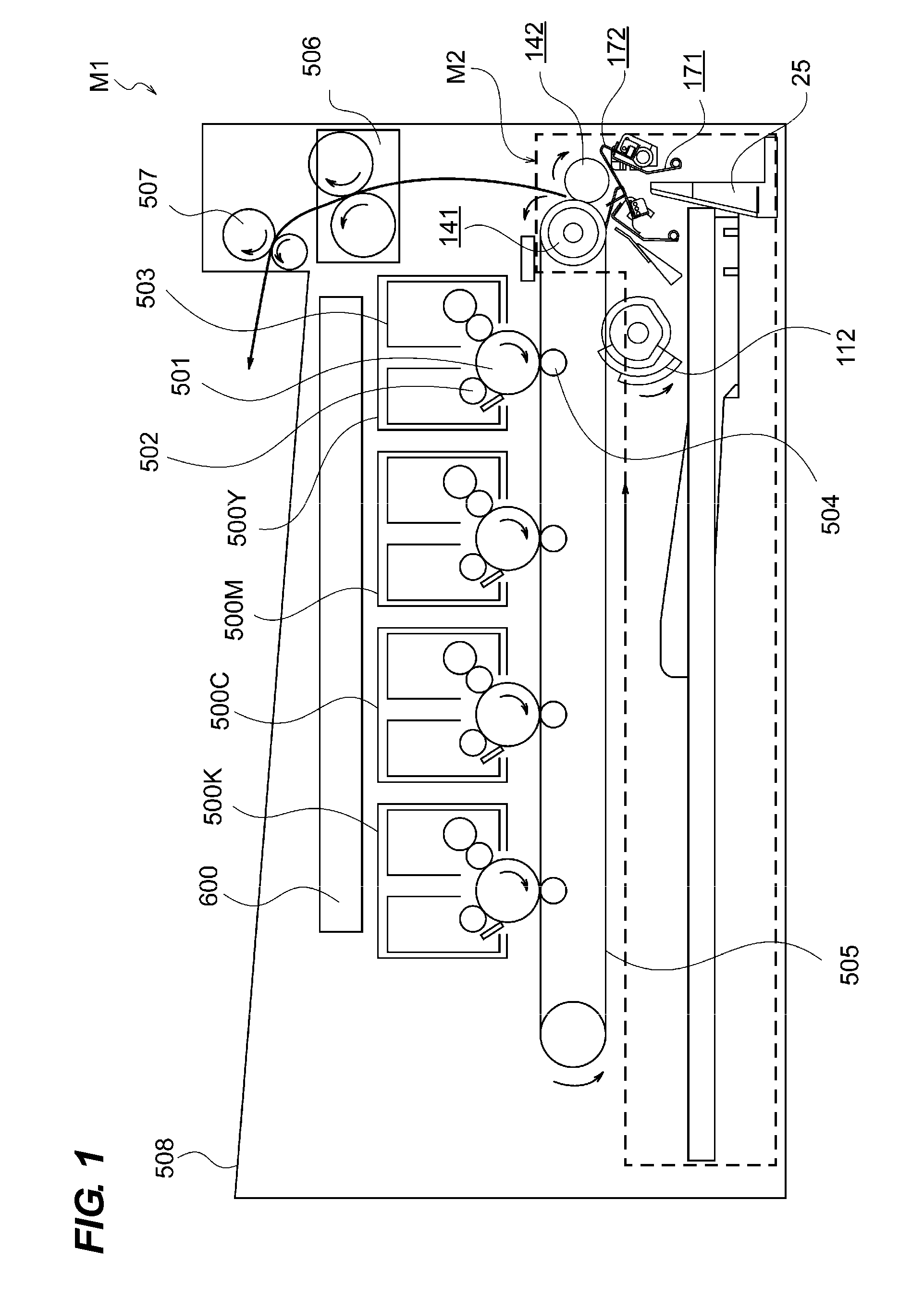
[0044]FIG. 1 is an entire schematic diagram illustrating an image forming apparatus including a sheet feeding device according to an embodiment of the invention. An image forming apparatus M1 of the embodiment has a configuration in which four image forming portions 500Y, 500M, 500C, and 500K forming images of yellow, magenta, cyan, and black are disposed. The image forming portions have the same configuration except that only the color of the toner forming the image is different. For example, the image forming portion will be described by exemplifying the yellow image forming portion 500Y.

[0045]In order to form an image, a photosensitive drum 501 is rotationally driven, and the surface thereof is charged by a charging roller 502. Then, a laser scanner unit 600 emits a laser beam from a light source (not illustrated) provided therein, and irradiates the photosensitive drum with the laser beam. Accordingly, a latent image is formed on t...


PUM


Abstract

A sheet feeding device includes: a tip end holding portion configured to hold a tip end of the fed sheet at a first position on the downstream side in the sheet feeding direction in relation to a separation portion; a guide portion configured to guide the sheet; a movement unit configured to move the tip end holding portion and the guide portion between the first position and a second position closer to a feeding portion in relation to the first position; a release portion configured to release the sheet held by the tip end holding portion when the tip end holding portion moves from the first position to the second position; and a conveying portion configured to convey the sheet released from the tip end holding portion at the second position and convey the sheet in an area near the feeding portion in relation to the first position.

Description

BACKGROUND OF THE INVENTION[0001]1. Field of the Invention[0002]The present invention relates to a sheet feeding device used in an image forming apparatus such as a copying machine, a facsimile machine, and a printer and an image forming apparatus including the same.[0003]2. Description of the Related Art[0004]Hitherto, an image forming apparatus such as a copying machine generally has a configuration in which a sheet cassette is set at a lower portion of an apparatus body and an image forming portion is disposed at the upside thereof. Accordingly, for example, as disclosed in U.S. Patent Application Publication No. 2010 / 226669 A1, a sheet feeding device used in an image forming apparatus forms a sheet conveying path so that a sheet substantially horizontally stacked on a stacking portion is pressed in the horizontal direction by a roller member from the rear side and is conveyed in the vertical direction. Accordingly, the sheet is conveyed to the image forming portion located above...

Claims


Application Information

Patent Timeline
IPC IPC(8): B65H3/06B65H7/20B65H7/02G03G15/00B65H1/14
CPCB65H3/0684G03G15/6529B65H7/20B65H7/02B65H1/14B65H3/0669B65H3/56B65H3/68B65H7/00B65H2403/421B65H2403/532B65H2404/1141B65H2405/1136B65H2511/20B65H2511/212B65H2511/22G03G15/6511B65H2220/01B65H2220/08
Inventor MATOBA, TAKESHITAMURA, MASASHIGE
Owner CANON KK
Learn More