Machine tool

a technology of machine tools and tools, applied in the field of machine tools, can solve problems such as complicated structure of pallet exchangers, and achieve the effect of easy checking or inspecting workpieces and increasing the swinging angle of the tabl

Inactive Publication Date: 2015-10-22
OKUMA CORP
View PDF6 Cites 19 Cited by
  • Summary
  • Abstract
  • Description
  • Claims
  • Application Information

AI Technical Summary

Benefits of technology

[0023]According to the fifth aspect of the present invention, for example, the workpiece on the table is less likely to hide behind the support portion placed in front of the table, and thus the user of the machine tool is less likely to have difficulty in checking or inspecting the workpiece on the table through the front surface of the body cover which has been opened by the first door. This makes it easier for the user of the machine tool to check or inspect the workpiece on the table.
[0024]According to the sixth aspect of the present invention, before the table starts swinging about the swing shaft or when the table swings about the swing shaft, the first rail member does not protrude

Problems solved by technology

This may complicate the structure of the pallet exchanger as a control unit that synchronizes the pallet moving base with the transfer mechanism, etc.
Moreover, the pallet ex

Method used


Image

  • Machine tool
  • Machine tool
  • Machine tool

Examples


first embodiment

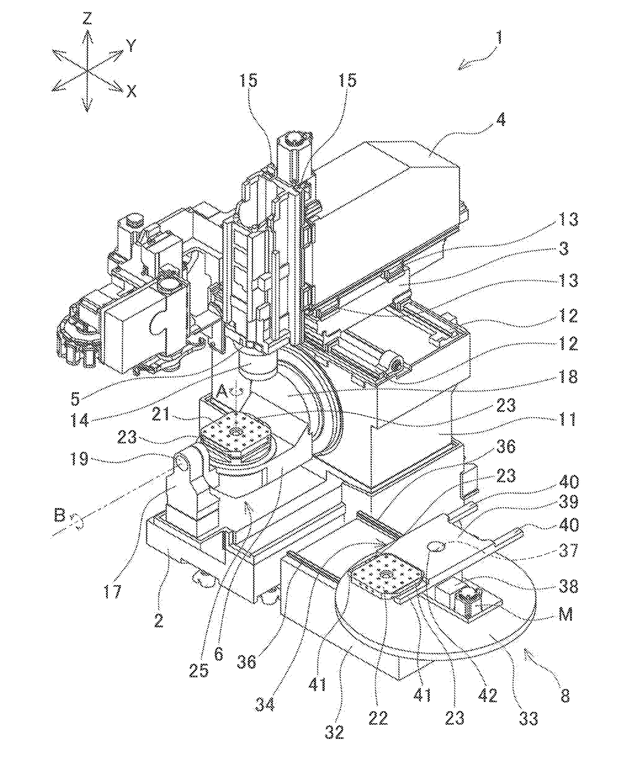
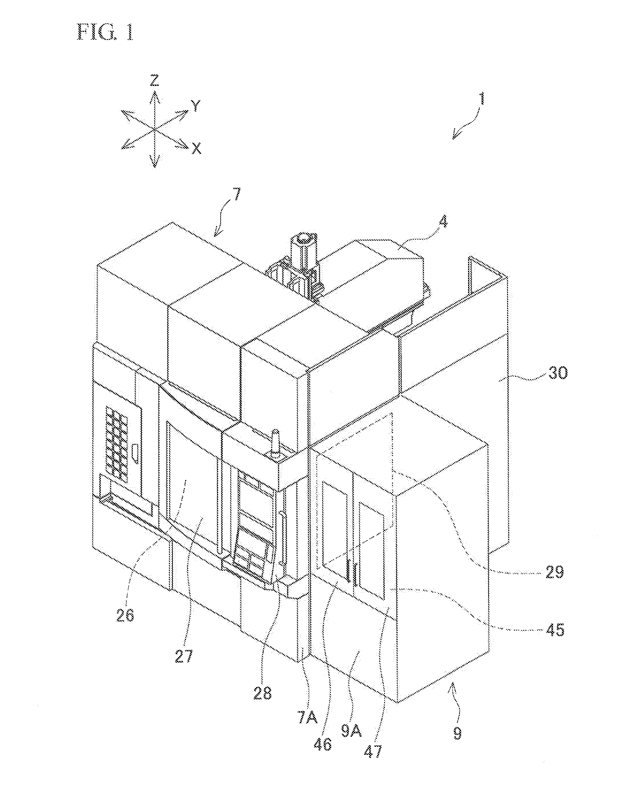
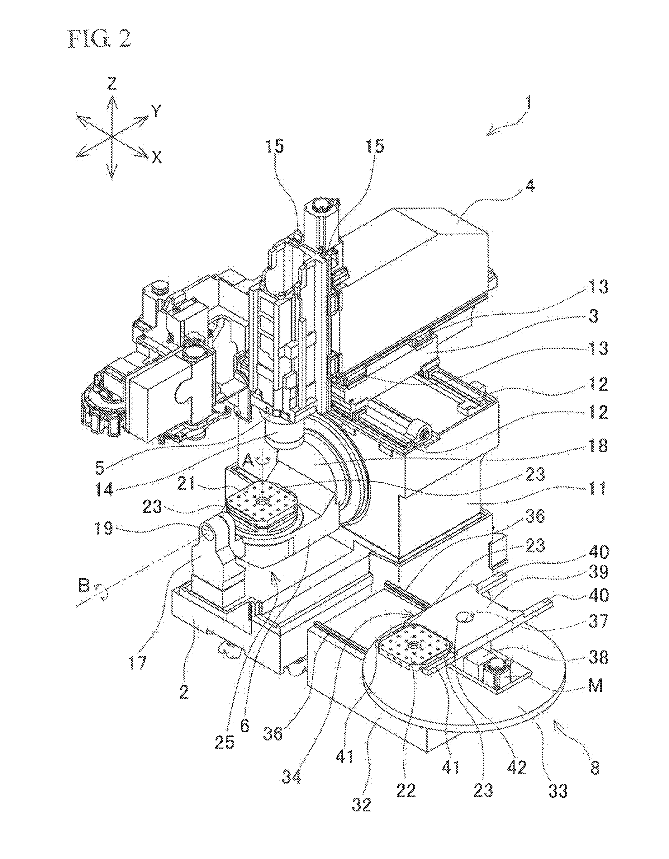
[0040]the present invention will be described with reference to FIGS. 1 to 8. A vertical machining center 1 shown in FIGS. 1 and 2 includes a bed 2, a saddle 3, a column 4, a spindle head 5, a table 6, a body cover 7, a pallet exchanger 8, and a side cover 9. The vertical machining center 1 is an example of the machine tool in the present invention.

[0041]As shown in FIG. 2, the bed 2 has a rectangular shape that is longer in the longitudinal direction (Y-axis direction) as viewed in plan, and is placed on the floor. A standing portion 11 is provided on the upper surface of the rear end part of the bed 2 so as to stand upward. The saddle 3 is provided over the upper surface of the standing portion 11 such that the saddle 3 can be guided by X-axis guide rails 12, 12 to move in the lateral direction (X-axis direction). The column 4 is provided over the upper surface of the saddle 3 such that the column 4 can be guided by a Y-axis guide member 13 to move in the Y-axis direction. The spi...


PUM


Abstract

A machine tool includes a pallet exchanger that is placed adjacent to one side of a body cover covering a workpiece machining space, and that exchanges a first pallet on which a machined workpiece is mounted and that is fixed to an upper surface of a table and a second pallet on which a workpiece to be machined is mounted. The pallet exchanger includes a turning member that has a first holding portion and a second holding portion formed in a pair and turns in a horizontal direction. The first holding portion is located at a first end of the turning member and holds the first pallet, and the second holding portion is located at a second end on the opposite side of the turning member from the first end and holds the second pallet.

Description

BACKGROUND OF THE INVENTION[0001]This application claims the benefit of Japanese Patent Application Number 2014-085769 filed on Apr. 17, 2014, the entirety of which is incorporated by reference.[0002]1. Field of the Invention[0003]The present invention relates to machine tools in which a machining space of the machine tool is covered by a body cover, and a pallet exchanger is placed adjacent to one side of the body cover and exchanges a first pallet on which a machined workpiece is mounted and a second pallet on which a workpiece to be machined is mounted. The first pallet is fixed to an upper surface of a table placed in the machining space.[0004]2. Description of Related Art[0005]For example, in a machine tool disclosed in Japanese Patent No. 4342474, a workpiece machining space is provided in a body of the machine tool and covered by a first cover, a table is placed in the machining space and a workpiece is fixed on an upper surface of the table. In the machine tool, a pallet exc...

Claims


Application Information

Patent Timeline
IPC IPC(8): B23Q7/02
CPCB23Q7/02B23Q1/44B23Q11/0891B23Q7/1431B23Q7/1494Y10T29/5196Y10T409/30392Y10T409/305824Y10T409/308288Y10T409/309576Y10T483/16Y10T483/1755B23Q1/5406B23Q1/626B23Q3/15766
Inventor MURATA, ATSUYA
Owner OKUMA CORP
Why Eureka
Try Eureka