Ultrasonic diagnostic apparatus and ultrasonic diagnostic method
a diagnostic apparatus and ultrasonic technology, applied in the field of ultrasonic diagnostic apparatus and ultrasonic diagnostic method, to achieve the effect of high accuracy
- Summary
- Abstract
- Description
- Claims
- Application Information
AI Technical Summary
Benefits of technology
Problems solved by technology
Method used
Image
Examples
first embodiment
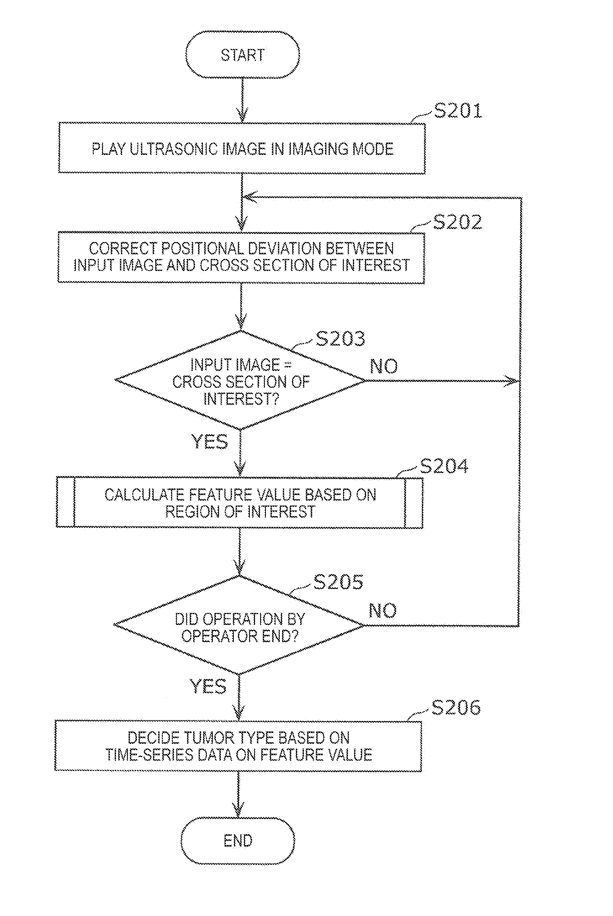
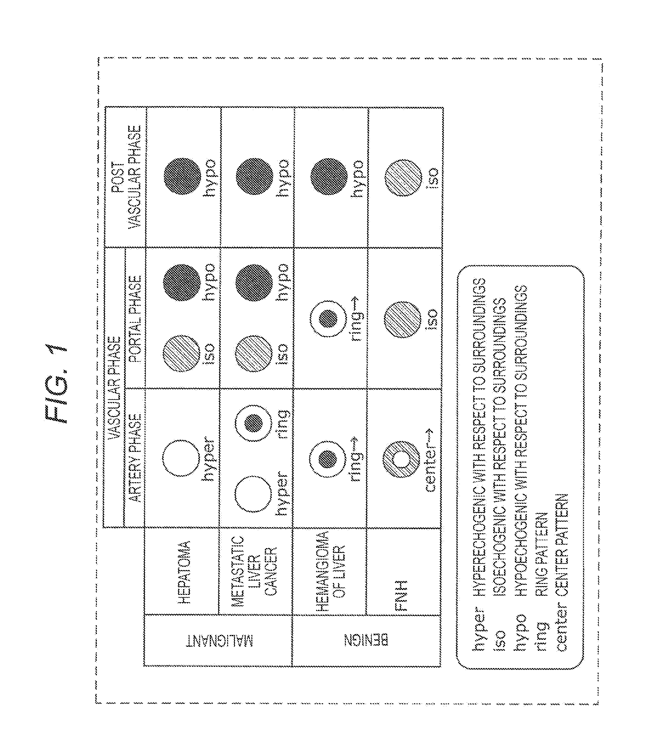
[0084]Discussed in this embodiment is an example which adopts feature values reflecting a luminance difference between a tumor region (target region) and a parenchyma region in an ultrasonic image, and imaging patterns (such as ring pattern, center pattern, and iso-pattern) in the tumor region to decide a type of a liver tumor with high accuracy. The “tumor” in this context refers to a tissue exhibiting properties different from those of other tissues, including both a benign tumor and a malignant tumor.
[0085]FIG. 3 is a block diagram illustrating a configuration of an ultrasonic diagnostic apparatus 100 according to this embodiment.
[0086]As illustrated in FIG. 3, an ultrasonic system according to this embodiment includes the ultrasonic diagnostic apparatus 100, an ultrasonic probe 101, an input device 110, and a display device 111. The ultrasonic diagnostic apparatus 100 includes an ultrasonic wave transmitting and receiving unit 102, an image forming unit 103, a data storing unit ...
second embodiment
[0186]According to the first embodiment discussed above, the feature value calculating unit 106 searches for a region where the derivative becomes the maximum. However, the feature value calculating unit 106 in this embodiment searches for a region where a luminance value becomes the minimum.
[0187]FIG. 14 is a flowchart showing a feature value calculating process according to this embodiment.
[0188]As illustrated in FIG. 14, the feature value calculating unit 106 searches for a region where a luminance value becomes the minimum within a tumor region (S311). More specifically, the feature value calculating unit 106 scans a search region 75 in the tumor region 70 to search for a region where the luminance value becomes the minimum as illustrated in FIG. 5. The luminance value in this context refers to an average of luminance values within the search region 75, for example. The luminance value may be a center value or a mode of the luminance values in the search region 75, for example. ...
third embodiment
[0191]Discussed in this embodiment is a modified example of the method for calculating the feature value r.
[0192]FIG. 16 is a flowchart showing a feature value calculating process according to this embodiment.
[0193]Initially, the feature value calculating unit 106 projects a luminance value of the tumor region 70 in the vertical direction and the horizontal direction as illustrated in FIG. 17 (S321). Projecting a luminance value in the vertical direction in this context refers to a process for calculating an average of luminance values of a plurality of pixels contained in pixel columns for each of the pixel columns in the tumor region 70. Similarly, projecting a luminance value in the horizontal direction in this context refers to a process for calculating an average of luminance values of a plurality of pixels contained in pixel rows for each of the pixel rows in the tumor region 70. This process may be executed for each pixel, or may be executed for each region containing a plura...
PUM
 Abstract
Description
Claims
Application Information
 - R&D
- Intellectual Property
- Life Sciences
- Materials
- Tech Scout
- Unparalleled Data Quality
- Higher Quality Content
- 60% Fewer Hallucinations
Browse by: Latest US Patents, China's latest patents, Technical Efficacy Thesaurus, Application Domain, Technology Topic, Popular Technical Reports.
© 2025 PatSnap. All rights reserved.Legal|Privacy policy|Modern Slavery Act Transparency Statement|Sitemap|About US| Contact US: help@patsnap.com


