
Combination Polycrystalline Diamond Bit and Bit Holder

a polycrystalline diamond and diamond technology, applied in the direction of cutting machines, earthwork drilling and mining, manufacturing tools, etc., can solve the problems of individual bits wearing or breaking off their shanks, needing replacement, and brittle polycrystalline diamond tips that are not suitable for degrading concrete highways, or curved highway stretches

Active Publication Date: 2015-10-15
THE SOLLAMI COMPANY
View PDF2 Cites 41 Cited by
  • Summary
  • Abstract
  • Description
  • Claims
  • Application Information

AI Technical Summary

Benefits of technology

The invention is a bit holder for road milling machinery. It is made of a cylindrical member with a groove on its distal end. This design has technical effects that improve the performance of the machinery.

Problems solved by technology

Additionally, it has been found that because of the harsh use environment, individual bits may wear or be broken off of their shanks and need replacement.
While the hardness of the polycrystalline diamond tip lengthens the useful life of the combined bit and bit holder shown in the '371 patent, such that the bit does not have to be removable from the bit holder, the combination includes a somewhat brittle polycrystalline diamond tip that is not suitable for use in degrading concrete highways, or curved highway stretches such as cloverleafs and the like.

Method used


Image

  • Combination Polycrystalline Diamond Bit and Bit Holder
  • Combination Polycrystalline Diamond Bit and Bit Holder
  • Combination Polycrystalline Diamond Bit and Bit Holder

Examples


first embodiment

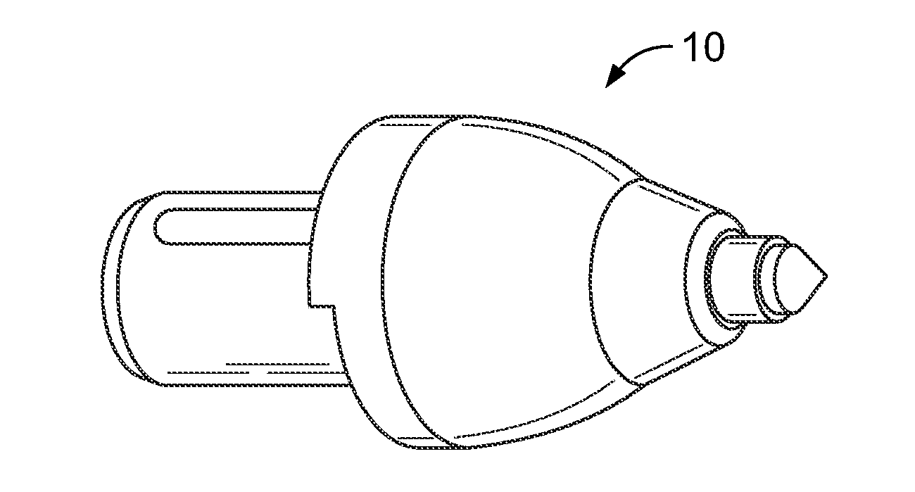
[0025]In this first embodiment, the shank 14 preferably includes a lower or first tapered portion 23 running axially from a stepped shoulder 24 adjacent the distal end of the shank upwardly or axially from the top or front of the shank where it terminates generally mid slot longitudinally, and includes an annular shoulder 25 separating this lower portion from an upper or second tapered portion 26 which extends from that shoulder generally to the top of the shank or forward terminations of the slots. From a position adjacent the top or upper termination of the slots, a generally cylindrical upper portion 27 of the shank extends towards a generally annular back flange 28 denoting the base of the upper body 13 of the bit holder 10.

[0026]In the preferred first embodiment 10, this generally annular base includes a pair of horizontal slots 30-30 generally perpendicular to the longitudinal axis of the combination bit / bit holder, one on either side of the generally annular base 13 into whic...

fourth embodiment

[0046]The second difference between the fourth embodiment and the preceding one is an annular cylindrical outer wall portion 96 adjacent the top of the first tapered portion of the shank 97. When it has been determined that the design parameters for the outward forces at the shank first tapered portion 98 have been met utilizing less than the whole available surface area, an annular cylindrical area 100 may be formed adjacent the upper end of the first tapered portion that keeps that area from contacting the bit block bore. The axial width of the cylindrical band may be varied to meet design criteria.


PUM

PropertyMeasurementUnit
wear resistanceaaaaaaaaaa
hardnessaaaaaaaaaa
distanceaaaaaaaaaa

Abstract

A quick change type bit / bit holder includes several different structures for holding the item in a bit block without the necessity of a fastener. The bit portion of the bit / bit holder combination includes a ductile steel insert with a polycrystalline diamond coated tungsten carbide bit positioned therein. The ductility of the steel insert acts as a shock absorber to allow the bit to successfully remove concrete as well as asphalt in a road milling machine.

Description

[0001]This application claims priority to and is a continuation-in-part of provisional patent application Ser. No. 61 / 716243 filed Oct. 19, 2012, and claims priority to and is a divisional of non-provisional application Ser. No. 13 / 801,012 filed Mar. 13, 2013 to the extent allowed by law.[0002]This invention relates generally to an integrally formed road milling bit and bit holders for mounting on road milling and other machines and, more particularly, to combinations of bit and bit holders having a polycrystalline diamond cutting tools as a forward leading tip of each.BACKGROUND OF THE INVENTION [0003]Originally, road milling equipment was utilized to smooth out bumps in the surface of a roadway or grind down the joinder of two adjacent concrete slabs that may have buckled. However, later these road milling machines, operated with a cylindrical drum having a plurality of bit blocks mounted thereon in herringbone or spiral fashion, and bit holders with bits on top thereof in turn mo...

Claims


Application Information

Patent Timeline
Patent Type & Authority Applications(United States)
IPC IPC(8): E21C35/183E21C35/19
CPCE21C35/183E21C2035/1806E21C35/19B28D1/188E21C35/197E21C35/18E21C35/1831
Inventor SOLLAMI, PHILLIP
Owner THE SOLLAMI COMPANY
Learn More