
Strain wave gearing unit

a gearing unit and wave technology, applied in the direction of gearing, gear lubrication/cooling, toothed gearings, etc., can solve the problems of foreign substances such as abrasion powder produced in the meshing portion infiltrating the raceway of the cross roller bearing, and avoiding negative effects, so as to reduce the life of the two gears and avoid negative effects. , the effect of reducing the life of the bearing

Active Publication Date: 2015-10-08
HARMONIC DRIVE SYST IND CO LTD
View PDF20 Cites 10 Cited by
  • Summary
  • Abstract
  • Description
  • Claims
  • Application Information

AI Technical Summary

Benefits of technology

The invention provides a strain wave gearing unit with a flat shape and prevents foreign substances from getting in the gear meshing portions and the bearing raceway. This is achieved by using a filter member made of a stacked double-layered filter with different porosities to trap foreign substances of different sizes and ensure the required lubricant fluidity. The filter member is fitted in a gap joined to both the sliding portions of the bearing and the meshing portions of the gears, effectively preventing damage to the gear surfaces and reducing the likelihood of negative effects such as reduced gear lifespan and bearing damage. The nonwoven fabric filter member is advantageous for flattening the gearing unit and easier machining.

Problems solved by technology

Therefore, there is a high risk that foreign substances such as abrasion powder produced in the sliding portions of the bearing will move to the meshing portions of the two gears through the annular gap formed between the inner race and the internally toothed gear, and infiltrate these meshing portions.
Similarly, there is a risk that foreign substances such as abrasion powder produced in the meshing portions of the two gears will infiltrate the raceway of the cross roller bearing.
For example, because the material of the bearing is harder than the material of the two gears, there is a concern that areas such as the tooth surfaces of the two gears will be scratched when abrasion powder and the like gets in the meshing portions of the two gears.

Method used


Image

  • Strain wave gearing unit
  • Strain wave gearing unit
  • Strain wave gearing unit

Examples


Embodiment Construction

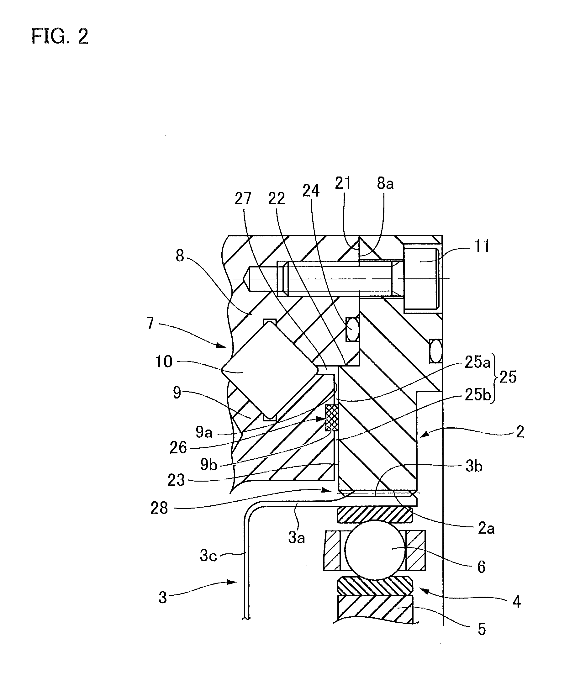
[0027]An embodiment of a strain wave gearing unit to which the present invention is applied is described with reference to FIGS. 1 and 2.

[0028]A strain wave gearing unit 1 comprises an annular rigid internally toothed gear 2 having a rectangular cross section. A cup-shaped flexible externally toothed gear 3 is coaxially disposed on the inner side of the internally toothed gear 2. A wave generator 4, which causes the externally toothed gear 3 to flex into an ellipsoidal shape and partially mesh with the internally toothed gear 2, is disposed on the inner side of the externally toothed gear 3.

[0029]The cup-shaped externally toothed gear 3 comprises a cylindrical barrel part 3a capable of radially flexing, external teeth 3b formed in the external peripheral surface portion of one end side of the cylindrical barrel part 3a, a diaphragm 3c extending radially inward from the other end of the cylindrical barrel part 3a, and an annular boss 3d formed continuous with the inner peripheral edg...


PUM


Abstract

A strain wave gearing unit is provided with an internal gear, which surrounds the periphery of a cup-shaped external gear, and a bearing. An annular gap is formed between the inner ring of the bearing and the internal gear. The gap communicates with the sliding portions of the bearing and the section where the two gears mesh. An annular filter member made of non-woven fabric is fitted in the gap. Foreign matter such as abrasion powder, which is contained in lubricant that flows in the gap, is trapped by the filter member. The present invention can prevent penetration of abrasion powder generated in the sliding portions into the meshing section via the gap.

Description

TECHNICAL FIELD[0001]The present invention relates to a strain wave gearing unit in which an internally toothed gear and a cup-shaped externally toothed gear are supported by a bearing so as to be capable of relative rotation. More specifically, the present invention relates to a strain wave gearing unit in which foreign substances such as abrasion powder produced in the bearing are prevented from infiltrating the meshing portions of the internally toothed gear and the externally toothed gear, and foreign substances such as abrasion powder produced in the meshing portions are prevented from entering the raceway of the bearing.BACKGROUND ART[0002]A strain wave gearing unit having a cup-shaped externally toothed gear is proposed in Patent Document 1. In this strain wave gearing unit, a cross roller bearing is disposed on the rear side of the cup-shaped externally toothed gear. A cylindrical unit housing is disposed so as to enclose the external periphery of the cup-shaped externally t...

Claims


Application Information

Patent Timeline
IPC IPC(8): F16H49/00F16H57/04
CPCF16H49/001Y10T74/19F16H57/0404F16H1/32F16H57/0482
Inventor ORII, DAISUKEKIYOSAWA, YOSHIHIDE
Owner HARMONIC DRIVE SYST IND CO LTD
Learn More