
Flexible Package With A Stable Structure

a flexible and stable technology, applied in the field of packaging, can solve the problems of rigid packages, occupying more space, and requiring additional expense and manufacturing effort, and achieve the effects of less displacement of the center of mass, less torque on the container, and improved stability

Inactive Publication Date: 2015-10-08
GLENROY
View PDF20 Cites 13 Cited by
  • Summary
  • Abstract
  • Description
  • Claims
  • Application Information

AI Technical Summary

Benefits of technology

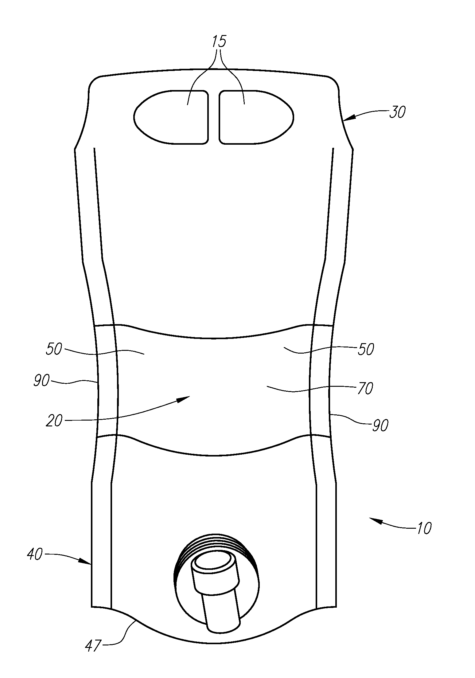
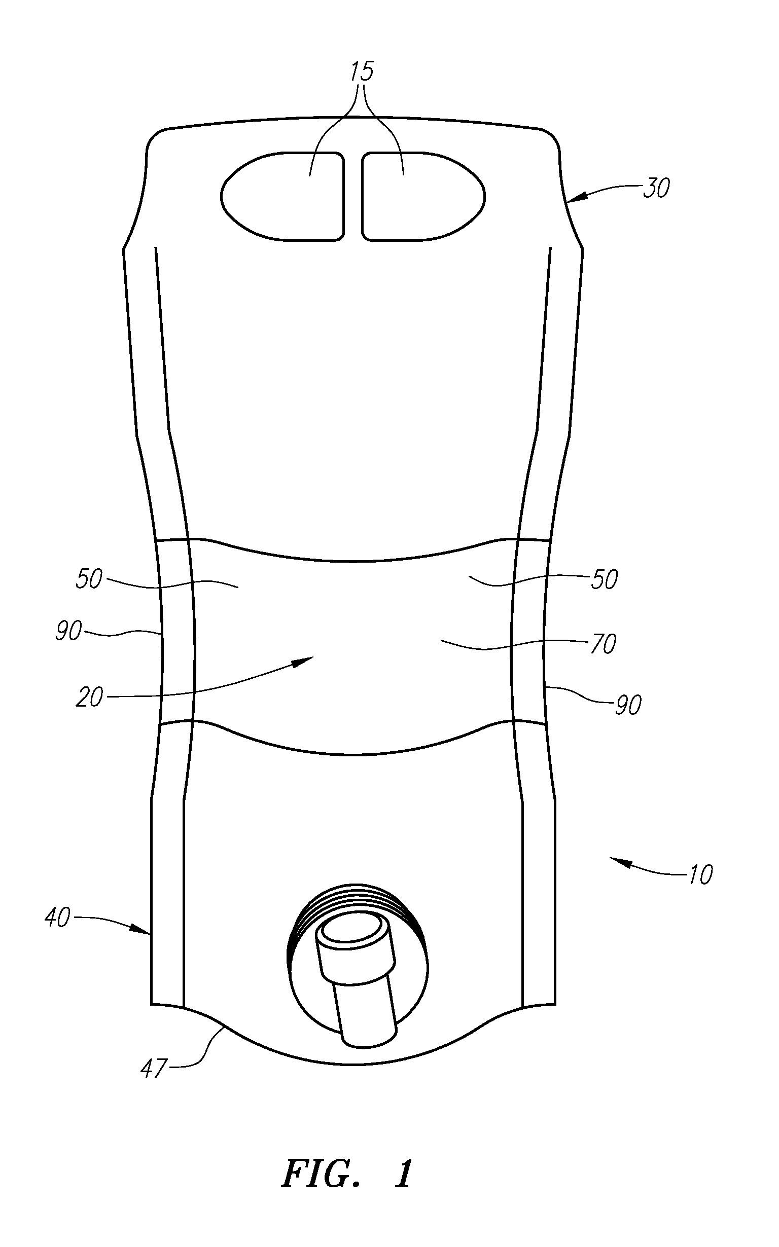
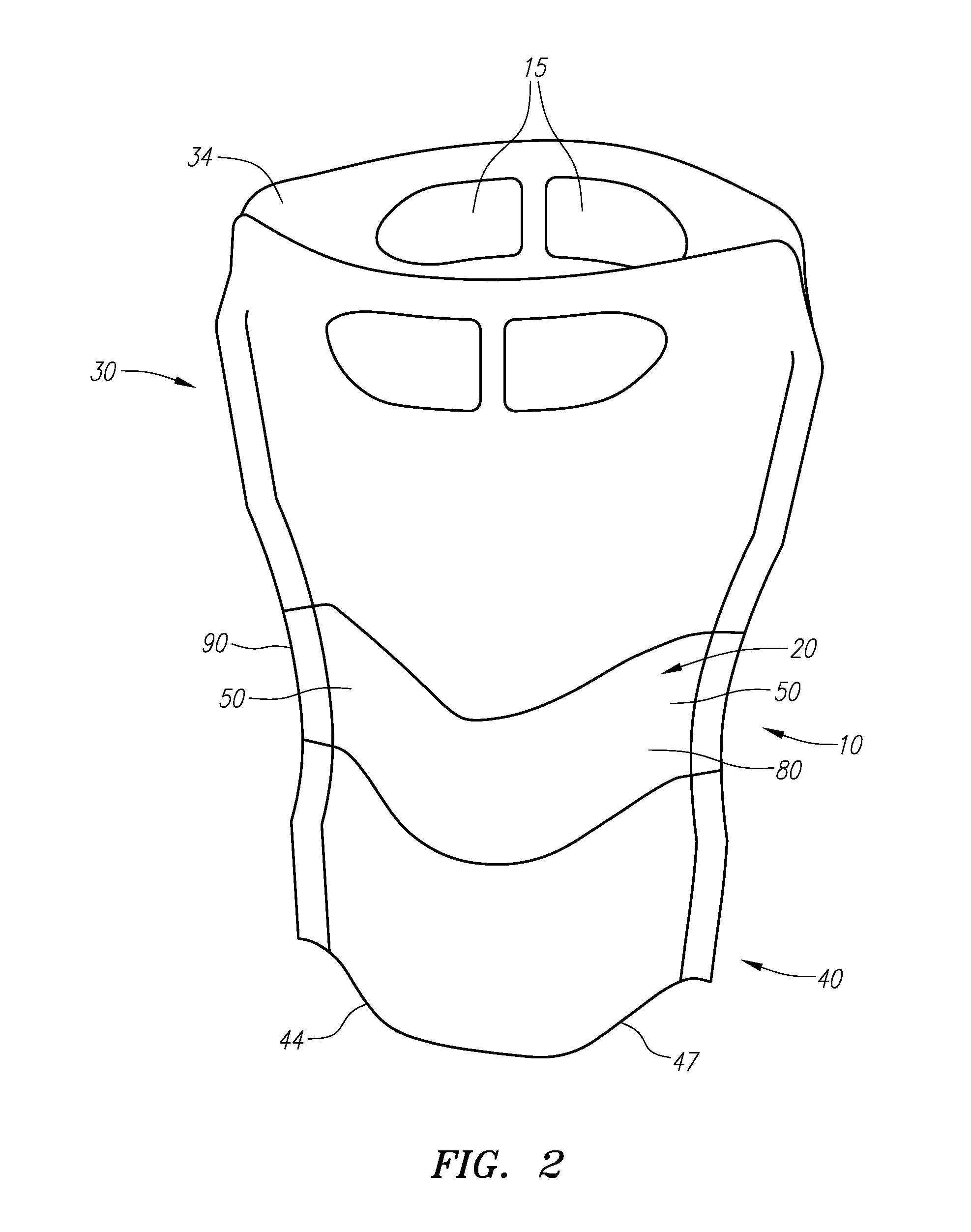
The present invention is about a flexible packaging with contoured sides to improve its stability. The contoured sides may include a narrowed or hourglass portion at or near the middle of the package, and curved or convex upper and lower sections. The contoured sides may help the package withstand perturbations such as indentations that may occur in the dispensing process or in the process of moving the package. The width of the seal that if formed when joining the front and rear panels may be increased to provide greater beam strength to the sides of the contoured shape. The bottom portion of the pouch containing the fluid may contact the surface on which the package rests, such that the weight of the package is not entirely borne by the bottom skirt or other bottom feature of the package. One or more strengthening ribs may be positioned within the seal area, providing additional structural support by supplying rigidity while allowing the overall packaging to remain flexible.

Problems solved by technology

Rigid packages, on the other hand, often involve additional expense and manufacturing effort.
Additionally, rigid packages often consume more space when stored or placed on retail shelves.
Rigid packaging also provides fewer options for customization and brand recognition.
Among them is the inability for the flexible packaging to retain stability and remain upright or stand in a vertical position.
Many existing flexible packages tend to fold over due to the weight of the fluid contained therein and / or the top-heavy nature of the packaging.
This inability to remain upright is a significant drawback.
And where a flexible package cannot remain upright on a shelf and serve that promotional purpose, sales may be hurt and retailers may discontinue buying the product.
A flexible package that is prone to folding over or collapsing may lack product integrity during the shipping and distribution cycle.
In particular, such a package could develop flexing or flex cracks during transit cycles where the package may experience a high degree of vibration leading to degradation of the film integrity and cause leaks.
In addition, flexible package that is prone to folding over or collapsing may be difficult to store or otherwise handle.
Furthermore, the end consumer may have difficulty dispensing fluid from a folded-over package leading to spillage and lack of repeat purchases.
Still further, because an unstable flexible package would tend to fold over at the same area, that area would tend to become an area of flex cracking in the film during distribution where handling and / or vibration would weaken the seals or film structures in those areas to cause leaks or pin holes.
The foregoing problems may not be a major concern with small packages that simply do not contain enough fluid to become top-heavy or otherwise unstable so as to fold over.
However, the foregoing problems are exacerbated for flexible packaging as the size or volume of the package increases.
This generally occurs because as the package increases in size or volume, the increased volume of fluid weighs more, which may lead to instability.
Furthermore, larger packages may become top heavy because of the weight of the fluid at or near the top of the packaging.
This in turn causes the instability problems described above because the package is more susceptible to fold over at or near its middle portion.
Instability problems may especially arise when the package experiences a perturbation or indentation that may occur when the package is moved or bumped.
For example, when the package is in the transit cycle, or when the package is placed on a retail shelf, the forces it experiences from this movement may cause it to fold over.
Repeat folding can lead to cracking in the flexible film material.
Alternatively, if a consumer opens a fitment to dispense the fluid, this perturbation may cause the package to fold over.
As another alternative, if a prospective consumer touches a package on a retail shelf, this indentation force may cause the package to fold over.
With such designs having straight edges, the top-heavy nature of the design and / or the weight of the liquid may cause the package to fold over or collapse as discussed above.
But despite these advances in packaging technology and the potential benefits, the inability for flexible packages, especially large packages, to remain stable and upright still exists.
However, the hourglass shapes used with these packages do not appear to be designed to address the instability issues discussed above, such as the gravitational or other forces associated with the fluid contained in the package.
In sum, the hourglass sides of existing packages do not appear to be designed to address forces and improve stability of the package so that it remains upright.
However, these larger pouches are often found in corrugated boxes where the box provides the stability and the flexible film structure is solely for containment within the box, and the graphics are on the exterior of the box and not the flexible pouch itself.
Another drawback of existing flexible packaging arises from the fact that the package has to be sufficiently wide in relation to its height such that the overall stability of the packaging is maintained.
But current linear or non-linear package designs do not allow for various package shapes and designs.
However, the ribs in existing packaging are typically not constructed to withstand the forces of increased fluid volumes for larger size packaging.
Moreover, the rib construction in existing packaging may be complex and require additional manufacturing steps or materials.
The manner in which many existing flexible packages engage the ground or surface on which they rest also contributes to their instability problems.
Because typical existing bottom skirts are thin, i.e., they generally have the thickness of the material used to make the package itself, such bottom skirts do not provide much stability and are prone to buckling.
This problem is exacerbated for larger packages containing more fluid, which imparts more weight on the bottom skirt.

Method used


Image

  • Flexible Package With A Stable Structure
  • Flexible Package With A Stable Structure
  • Flexible Package With A Stable Structure

Examples


Embodiment Construction

[0038]In general, the flexible packaging of the current invention may contain liquids or other pourable material, and is preferably stable and may stand up or otherwise retain its vertical orientation when filled, when its contents are dispensed, when the package is at rest and / or when the package is moved or experiences a perturbation. The current invention also preferably avoids expensive or labor intensive manufacturing processes. The current invention may also provide marketing functions and may provide a packaging with dimensions that may be customized.

[0039]The current invention is now described with reference to the figures. Components appearing in more than one figure bear the same or similar reference numerals.

[0040]Package or packaging 10 is first generally described with reference to FIGS. 1-4. Packaging 10 may be 12″ tall or taller, though other heights may be used and the invention is not limited to this example. Packaging 10 may be approximately 7″ wide or wider, thoug...


PUM

PropertyMeasurementUnit
widthaaaaaaaaaa
widthaaaaaaaaaa
volumesaaaaaaaaaa

Abstract

A packaging for containing fluids or other pourable materials is described. The packaging includes contoured sides that experience an outward force due to the gravitational forces of the fluid contained in the package thereby helping the package to remain upright. The package may include a bottom gusset that rests on the surface to provide stability. The package may include strengthening ribs.

Description

FIELD OF THE INVENTION[0001]The present invention generally relates to packaging that may contain fluids and other pourable materials, including packaging made of flexible material in a configuration that allows the packaging to remain stable and / or in an upright position. The present invention also relates to such packaging used to contain larger volumes of fluids or other pourable materials.BACKGROUND OF THE INVENTION[0002]Fluids and other pourable materials are frequently contained in packaging that allows the user to dispense the contents. Such packaging has been made of rigid and flexible materials, but flexible packaging has a number of advantages over rigid packaging.[0003]For example, flexible packaging may be made from a roll of material having sections that may be joined together. As such, flexible packaging may be manufactured using a variety of cost-efficient materials, and may allow for simpler manufacturing and lower cost. Flexible packaging may also comprise materials...

Claims


Application Information

Patent Timeline
Patent Type & Authority Applications(United States)
IPC IPC(8): B65D33/06B65D33/02
CPCB65D33/02B65D33/06B65D75/008B65D75/5877
Inventor DYTCHKOWSKYJ, DAVE
Owner GLENROY
Learn More