Method for Adjusting Volume of Combustion Chamber of Engine

Active Publication Date: 2015-10-01
DMG MORI SEIKI CO LTD
View PDF3 Cites 11 Cited by
  • Summary
  • Abstract
  • Description
  • Claims
  • Application Information

AI Technical Summary

Benefits of technology

The present invention aims to solve the problems in the related art. It provides a solution that can address the problems that have been faced in the past.

Problems solved by technology

However, this method is inefficient because of the intervention of manual work.
However, the method described in the above literature only measures the distance between one point of the reference surface and the mating surface, so the accuracy is not so high.

Method used


Image

  • Method for Adjusting Volume of Combustion Chamber of Engine
  • Method for Adjusting Volume of Combustion Chamber of Engine
  • Method for Adjusting Volume of Combustion Chamber of Engine

Examples


first embodiment

Example of Arrangement of Machine Tool Including Laser Displacement Meter

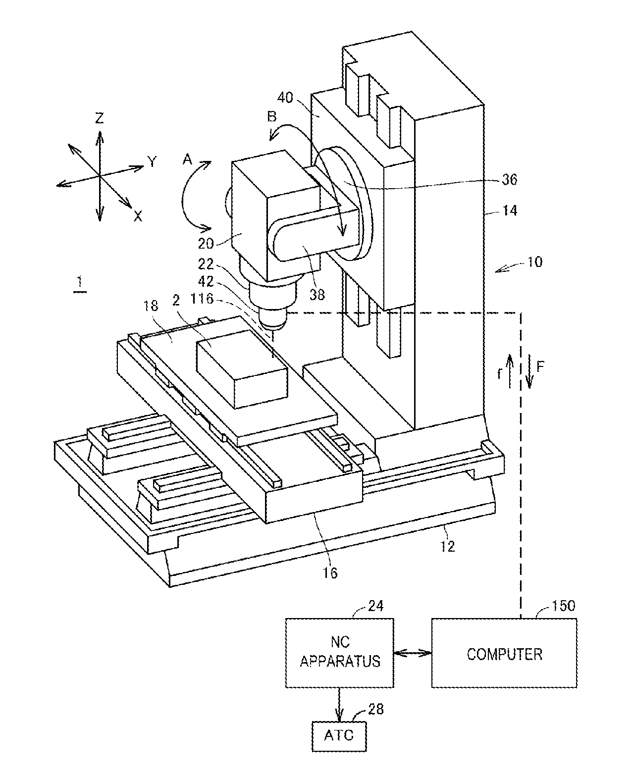
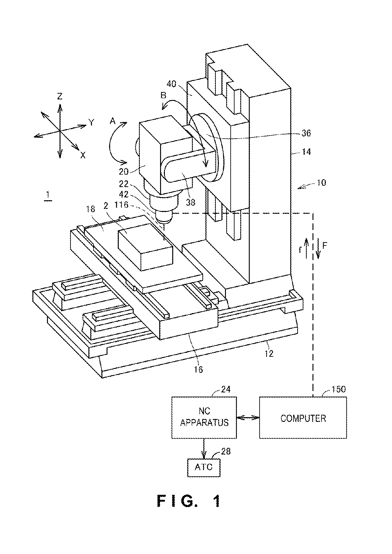
[0040]FIG. 1 is a perspective view schematically showing an example of a machine tool including a displacement meter used in the first embodiment of the present invention. A case in which the machine tool is a vertical machining center will be explained below, but the machine tool may be of another type such as a horizontal machining center. Further, a non-contact displacement meter using a laser will be exemplified as the displacement meter, but the displacement meter may be of a contact type.

[0041]Referring to FIG. 1, a machine tool 1 includes a processing apparatus 10, an NC (Numerical Control) apparatus 24, an ATC (Automatic Tool Changer) 28, and a computer 150.

[0042]The machining apparatus 10 includes a bed 12, a column 14 set on the bed 12, a spindle head 20 including a spindle 22, and a saddle 16 including a table 18.

[0043]The column 14 is set on the bed 12, and includes a back support 40 movable in the ...

second embodiment

[0083]In the second embodiment of the present invention, the cutting method and cutting amount of a mating surface 202 of a cylinder head 200 are decided by comparing measurement data 166 with three-dimensional shape data 168. The second embodiment is the same as the first embodiment in this regard, but is different from the first embodiment in the data comparison method. This will be explained in detail with reference to the drawings.

[0084]FIGS. 9A to 9C are sectional views for explaining a method of deciding the cutting amount and cutting direction of the mating surface of the cylinder head in the second embodiment. In FIGS. 9A to 9C, a broken line represents a surface shape based on each of measurement values 220, and a solid line represents a design shape 222 based ort the three-dimensional shape data 168.

[0085]Referring to FIG. 9A, first, a data processor 158 in FIG. 2 fits the design shape 222 of the mating surface 202 with respect to the respective measurement values 220 of t...

third embodiment

[0095]The third embodiment according to the present invention is different from the first and second embodiments in that a line laser displacement meter configured to emit a line-shaped laser beam is used. In FIG. 3 which is a view showing the arrangement of the laser displacement meter, the lens 114 of the light emitter 110 is replaced with, for example, a cylindrical lens in the case of the line laser displacement meter. In this arrangement, the light emitter emits a line-shaped laser beam. As a light receiver 120, a two-dimensional image sensor is used instead of the linear image sensor.

[0096]FIGS. 11A and 11B are views for explaining the measurement principle of the line laser displacement meter. As shown in FIG. 11A, a measurement target object 2 is irradiated with a band-shaped (line-shaped) laser beam 116A from a light emitter 110A. The light scattered by the measurement target object 2 is condensed through a light receiving lens 118 into not a spot shape but a line shape on ...


PUM

PropertyMeasurementUnit
Volumeaaaaaaaaaa
Shapeaaaaaaaaaa

Abstract

In order to adjust the volume of the combustion chamber with high accuracy, a cylinder head 200 includes a recess 204 constituting part of the combustion chamber of the engine and a mating surface for a cylinder block. The recess 204 includes a plurality of openings to which a plurality of specific members are attached respectively. The mating surface 202 is formed to have a cutting stock with respect to three-dimensional shape data of the cylinder head 200 designed to have a target combustion chamber volume. The adjusting method further comprises measuring the surface shape of the recess and the shape of the mating surface around the recess by successively changing the irradiation position of a laser beam using a line laser displacement meter. The adjusting method further comprises removing data of regions equivalent to the plurality of openings from measurement data by comparing the measurement data obtained by the line laser displacement meter with the three-dimensional shape data. The adjusting method still further comprises: calculating the volume of the recess 204 based on the measurement data from which the regions equivalent to the plurality of openings are removed; and deciding the cutting amount of the mating surface 202 by comparing the calculated volume of the recess 204 with a volume of the recess 204 based on the three-dimensional shape data.

Description

BACKGROUND OF THE INVENTION[0001]1. Field of the Invention[0002]The present invention relates to a method for adjusting the volume of the combustion chamber of an engine.[0003]2. Description of the Related Art[0004]The volume of a combustion chamber in art automobile engine greatly influences the combustion characteristics of fuel and the performance of the engine. Making the volume of the combustion chamber fall within a predetermined range is therefore necessary. More specifically, the volume of the recess of a cylinder head constituting part of the combustion chamber is measured, and a mating surface for a cylinder block or the recess is machined in accordance with the measurement result. By this machining process, the volume of the combustion chamber can be adjusted.[0005]As a conventional method of obtaining the volume of the recess of the cylinder head, a method of filling the valve hole of a cast cylinder head with clay or the like, pouring kerosene into the recess of the cyl...

Claims


Application Information

Patent Timeline
IPC IPC(8): G01B11/28B23C3/00
CPCG01B11/285B23C2215/242B23C3/00F02F1/24G05B19/4097G05B2219/37275Y10T29/4927Y02P90/02
Inventor NISHIKAWA, SHIZUONAKAO, HIROKI
Owner DMG MORI SEIKI CO LTD
Why Eureka
Try Eureka