Linkage control device and blood gas analyzer adopting same

a blood gas analyzer and linkage control technology, applied in the field of medical devices, can solve the problems of increasing the cost of switch elements and circuit control, unreliability of linkage effect among switches, and inability to provide a stable linkage guarantee, etc., to achieve stable and accurate linkage control, reduce cost, and minimize the effect of cost without disorder

Active Publication Date: 2015-09-17
EDAN INSTR
View PDF6 Cites 6 Cited by
  • Summary
  • Abstract
  • Description
  • Claims
  • Application Information

AI Technical Summary

Benefits of technology

[0007]In order to overcome the above-mentioned disadvantages, to achieve the best control effect, to conduct precise control of the time sequence of a variety of liquid and gas switches, and to minimize the cost without disorder caused by mutual effect, a linkage control device, capable of providing stable and accurate linkage control with lower cost and simpler structure, is provided.

Problems solved by technology

Mechanical switches in sophisticated equipment are unable to achieve linkage control of each switch by manual operation, and if solenoid valves are used to control each switch, for one thing, there are too many valves, signal input channels and signal output channels arranged on a control panel and used for controlling valves correspondingly increase so that the linkage effect among switches becomes unreliable; for another, too many solenoid valves increase the cost of switch elements and the cost of circuit control.
Therefore, in case of higher requirements for linkage, several above-mentioned switch control structures are unable to provide a stable linkage guarantee in addition to relatively high cost.
However, the new-type cam switch cannot be used for more switch control structures, in particular to precise medical equipment with many switches, and is unable to conduct accurate linkage control of switches.
With the development of technology, control of switches in precise medical equipment is increasingly demanding.

Method used


Image

  • Linkage control device and blood gas analyzer adopting same
  • Linkage control device and blood gas analyzer adopting same
  • Linkage control device and blood gas analyzer adopting same

Examples


Embodiment Construction

[0037]In order to make the objective, the technical scheme and advantages of the invention clearer, further detailed description of the invention is made as below in combination with the accompanying drawings and embodiments. It shall be understood that, these embodiments are only used for explaining instead of limiting the invention.

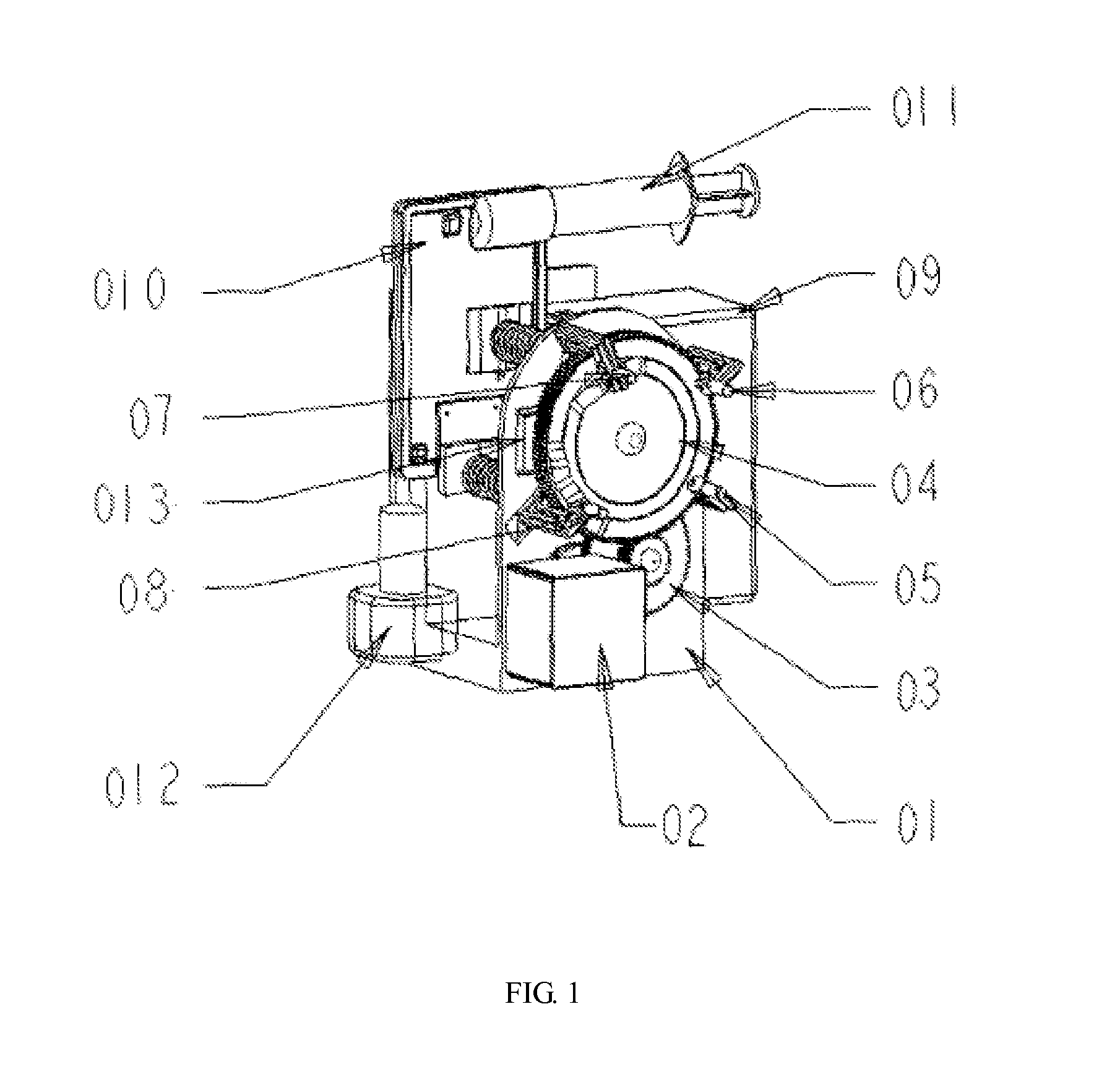
[0038]Further detailed description of the invention is made by taking the blood gas analyzer as an example (as shown in FIG. 1).

[0039]The blood gas analyzer includes: a valve control device, a reagent pack device, a test card, a vacuum pump and a main frame; the valve control device, the reagent pack device and the vacuum pump are arranged on the main frame; the cam linkage structure is arranged on the main frame; the test card and the reagent pack are inserted between the bracket and the valve components; and the test card and the reagent pack device are connected with the vacuum pump.

[0040]A linkage control device applied to a blood gas analyzer inclu...


PUM

PropertyMeasurementUnit
eccentric angleaaaaaaaaaa
flexibleaaaaaaaaaa
linkage structureaaaaaaaaaa

Abstract

Disclosed are a linkage control device and a blood gas analyzer adopting the linkage control device. The linkage control device comprises a power unit and a rotating component (4) provided with bosses (41, 42). The power unit generates power to drive the rotating component (4) to rotate. The linkage control device further comprises valve components (5, 6, 7, 8), a signal control unit, sensing switches, and sensing pins (43, 44, 45, 46). The valve components (5, 6, 7, 8) are matched with the bosses (41, 42) of the rotating component (4) in a pushing manner. The signal control unit controls the start or stop of the power unit. The sensing switches are connected to the signal control unit via signals. The sensing pins (43, 44, 45, 46) are arranged in pair with the sensing switches and are arranged on the rotating component (4).

Description

[0001]This application claims the benefit of Chinese patent application No. 201210241945.3, filed Jul. 13, 2012, which is hereby incorporated by reference in its entirety.FIELD OF THE INVENTION[0002]The invention relates to the field of medical apparatus, in particular to a linkage control device in the field of medical apparatus; the invention also relates to a blood gas analyzer.BACKGROUND[0003]Switch control structures are widely used in machinery and equipment; the current switch control mode on the market mainly relies on electromagnetic force switches or mechanical switches to achieve the on-off control of liquid circuits, gas circuits and electric circuits, etc. The direct point-to-point control mode can realize effective and short-time control of switches to be controlled. For example, machine power switches or pipe valve switches and so on can use mechanical switches to realize manual control or use electromagnetic switches to achieve automatic control of electric circuits....

Claims


Application Information

Patent Timeline
Patent Type & Authority Applications(United States)
IPC IPC(8): G01N35/00F16K1/24
CPCG01N35/00712G01N35/00693F16K1/24G01N33/4925F01L1/042Y10T436/115831F01L2305/00
Inventor HUANG, GAOXIANGZHAO, ZHIXIANG
Owner EDAN INSTR
Why Eureka
Try Eureka