[0009]An example method according to the present invention for determining the roll angle for occupant protection devices may have the
advantage over the related art that the roll angle may be estimated continuously with the help of the signals of a transverse acceleration sensor and a
vertical acceleration sensor, independently of the
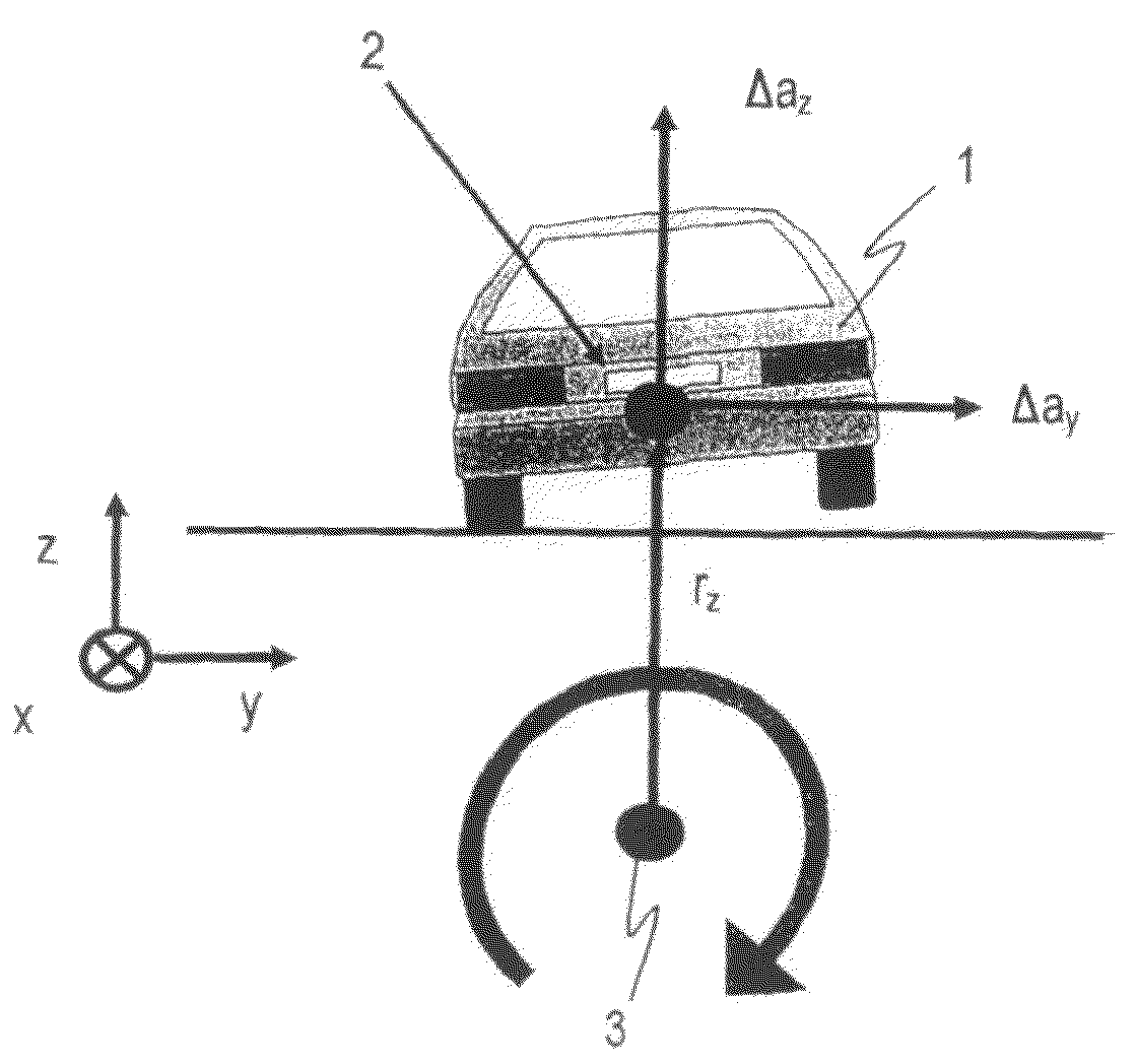
roll rate sensor and without restriction of the roll angle range, and may be made available at an early point in time to at least one deployment method for occupant protection devices. Through the example method according to the present invention, additional driving dynamics quantities are ascertained for calculation of the centripetal acceleration, including a vehicle speed, a
yaw angle and a float angle, so that the estimate of the roll angle is advantageously improved. These additional driving dynamics sensor data may be made available, for example, by other sensor units in the vehicle, for example, an electronic stability program
system (ESP
system). On the whole, the example method according to the present invention may advantageously yield a more accurate and more stable direct roll angle estimate, in particular in the range of small roll angles. Due to the more accurate and more stable roll angle made available, the subsequent deployment methods for occupant protection systems are able to detect vehicle rollovers promptly, making it possible to ensure that safety devices such as
seat belt tighteners, head airbags, window airbags and roll bars are activated promptly and therefore the risk of injury to the occupants is reduced. The example method according to the present invention for determining the roll angle thus advantageously allows an improvement in the calculation of deployment decisions for occupant protection systems.
[0010]As an additional
advantage, the example method according to the present invention for determining the roll angle increases the robustness of subsequent deployment methods, in particular in the range of small roll angles, and improves their reset performance. Therefore, improved deployment efficiency is advantageously achievable, stable driving situations and misuse are more recognizable, and inadvertent deployment of irreversible restraining devices may be prevented. The combination with sensor systems already integrated into the vehicle yields an increased benefit here with regard to the stability and robustness of the deployment method, so that rollover detection in off-road vehicles in particular may be improved due to the very robust deployment method. On the basis of the vehicle design for off-road use, in comparison with normal street traffic, increased demands with respect to robustness are made of the deployment method for detection of misuse.
[0011]Furthermore, the example method according to the present invention for estimating the roll angle may also be used in addition to a
roll rate sensor to advantageously support the roll angle estimate via the roll rate sensor as an alternative path and / or may be used as a plausibility check on the deployment decision. Therefore, the deployment and reset behavior of the deployment methods for occupant protection systems are further improved by the additional option of roll angle determination.
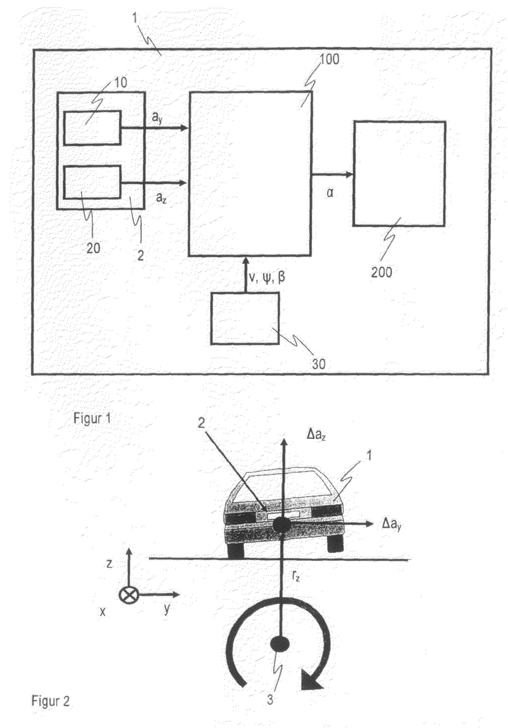
[0012]An example device according to the present invention for determining the roll angle for occupant protection devices may have the
advantage that two acceleration sensors are used for detecting the transverse acceleration and the vertical acceleration and an analyzer unit estimates the roll angle of the vehicle based on the transverse acceleration and vertical acceleration thereby detected, so the roll angle sensor may be omitted. To improve the estimate of the roll angle, the analyzer unit analyzes data from at least one additional sensor unit in the vehicle, this sensor unit ascertaining additional driving dynamics data and supplying the data for calculation of a centripetal acceleration. The driving dynamics data include a vehicle speed, a
yaw angle and a float angle. Since a roll rate sensor is no longer necessary to estimate the roll angle, the cost of the particular
control unit may be reduced by omitting the roll rate sensor. If the example device according to the present invention is used as an alternative path and to support the roll angle calculation by the roll rate sensor, then two alternative paths are advantageously available for determining the roll angle, thus allowing an increase in the robustness of the deployment method for occupant protection devices.
[0015]The example method and device according to the present invention for determining the roll angle for occupant protection devices show the great potential for improvement in the direct calculation of the roll angle when additional sensor information is used to improve the measured values of the central sensors via correction factors and alternatively to calculate quantities of the equation
system for the roll angle calculation, such as the centripetal acceleration. This improves the accuracy of the roll angle estimate, in particular at low roll angle values and with vibrations in the vehicle suspension systems occurring when driving over
road surface irregularities or in the case of
active steering movements on the part of the driver. In addition, the accuracy of the centripetal acceleration, estimated on the basis of the additional sensor data, in the low roll angle range is improved, thereby making it possible to reduce fluctuations in the estimated absolute roll angle.

