
Thin dual-aperture zoom digital camera

a digital camera and aperture zoom technology, applied in the field of digital cameras, can solve the problems of preventing fast reliable fusion of tele and wide images, aperture zoom cameras relating to their height, and camera height of around 9.8 mm, so as to improve the impact resistance and reduce the total thickness , the effect of reducing the difference between ttl and the difference between the two

Active Publication Date: 2015-08-27
COREPHOTONICS
View PDF7 Cites 42 Cited by
  • Summary
  • Abstract
  • Description
  • Claims
  • Application Information

AI Technical Summary

Benefits of technology

This patent is about thin cameras that have a zoom feature and are resistant to drops and impacts. These cameras also have a smaller size and a smaller difference between the width and tele cameras. Additionally, they have improved compensation for shaking.

Problems solved by technology

One problem with such cameras may arise from mishaps such as drop impact.
The latter may cause a relative movement between the two cameras after system calibration, changing the pixel matching between Tele and Wide images and thus preventing fast reliable fusion of the Tele and Wide images.
Another problem with dual-aperture zoom cameras relates to their height.
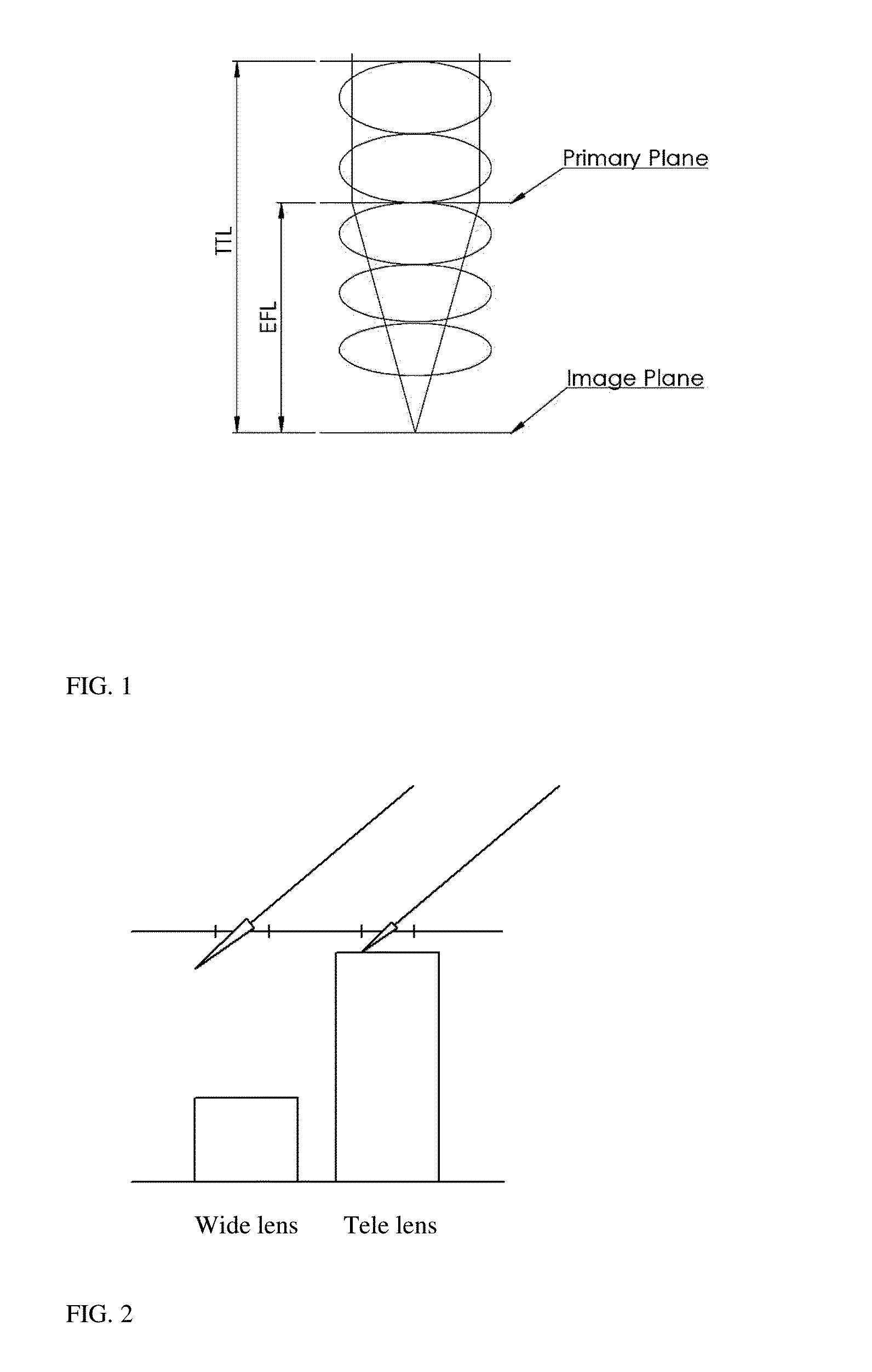
The incorporation of a 9.1 mm lens in a smartphone camera would lead to a camera height of around 9.8 mm, which is unacceptable for many smartphone makers.
4.55 mm) between the Wide and Tele cameras can cause shadowing and light-blocking problems, see FIG. 2.
A third problem relates to the implementation of standard optical image stabilization (OIS) in a dual-aperture zoom camera.
Camera tilt causes image blur.
Since as shown above a dual-aperture zoom camera may include two lenses with significantly different EFLs, it is impossible to move both lenses together and achieve optimal tilt compensation for both Tele and Wide cameras.
That is, since the tilt is the same for both cameras, a movement that will cancel the tilt for the Wide camera will be insufficient to cancel the tilt for the Tele camera.
Assigning a separate OIS actuator to each camera can achieve simultaneous tilt compensation, but at the expense of a complicated and expensive camera system.

Method used


Image

  • Thin dual-aperture zoom digital camera
  • Thin dual-aperture zoom digital camera
  • Thin dual-aperture zoom digital camera

Examples


Embodiment Construction

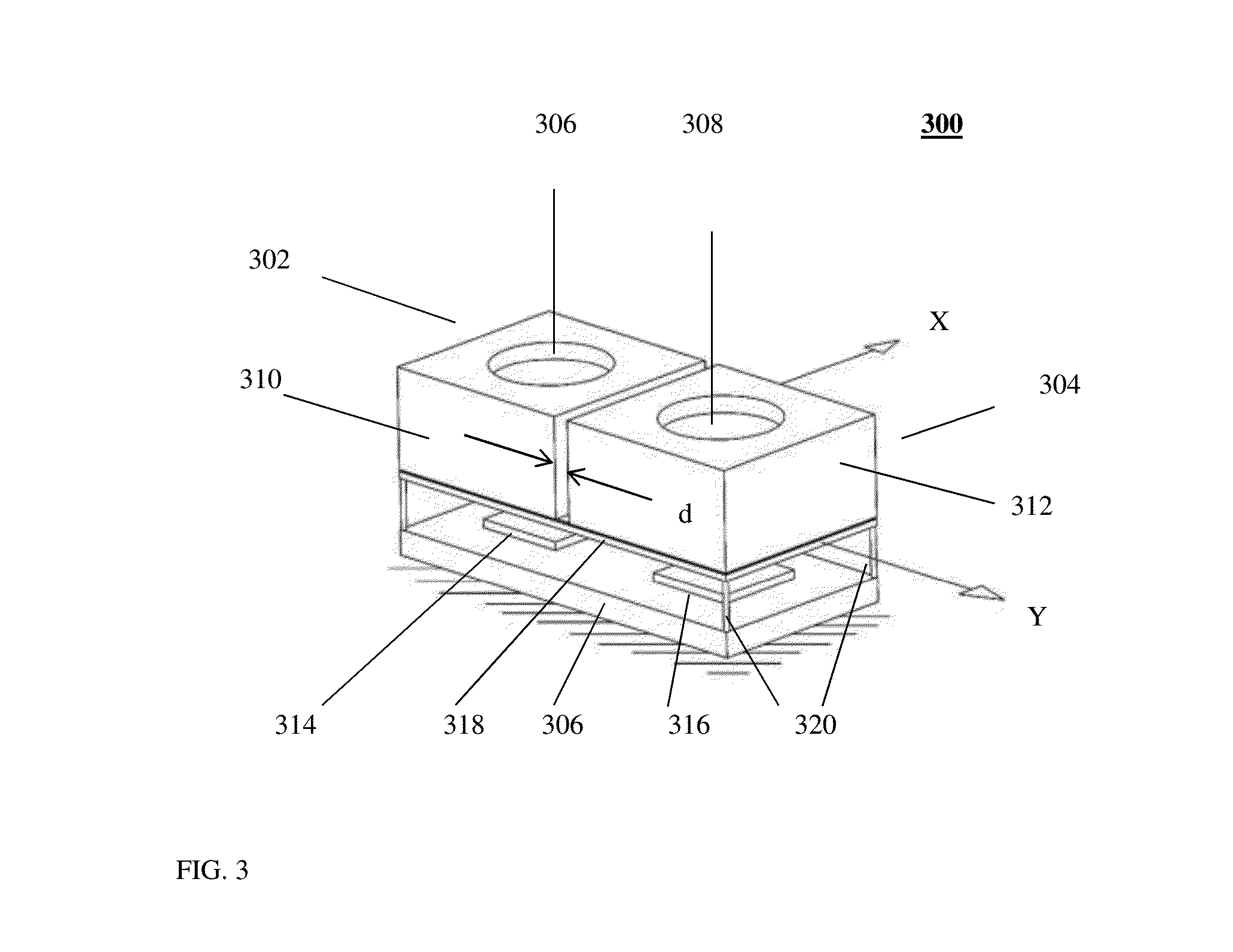
[0018]The present inventors have determined that camera movement (due to exemplarily, but not limited to mishaps such as drop impact) can be avoided or minimized by mounting the two cameras directly on a single printed circuit board and by minimizing a distance “d” therebetween. FIG. 3 shows an embodiment of a dual-aperture camera 300 that includes two cameras 302 and 304 mounted directly on a single printed circuit board 306. Each camera includes a lens assembly (respectively 306 and 308), an actuator (respectively 310 and 312) and an image sensor (respectively 314 and 316). The two actuators are rigidly mounted on a rigid base 318 that is flexibly connected to the printed board through flexible elements 320. Base 318 is movable by an OIS mechanism (not shown) controlled by an OIS controller 402 (FIG. 4). The OIS controller is coupled to, and receives camera tilt information from, a tilt sensor (exemplarily a gyroscope) 404 (FIG. 4). More details of an exemplary OIS procedure as di...


PUM

PropertyMeasurementUnit
Lengthaaaaaaaaaa
Distanceaaaaaaaaaa
Lengthaaaaaaaaaa

Abstract

A dual-aperture zoom camera comprising a Wide camera with a respective Wide lens and a Tele camera with a respective Tele lens, the Wide and Tele cameras mounted directly on a single printed circuit board, wherein the Wide and Tele lenses have respective effective focal lengths EFLW and EFLT and respective total track lengths TTLW and TTLT and wherein TTLW / EFLW>1.1 and TTLT / EFLT<1.0. Optionally, the dual-aperture zoom camera may further comprise an optical OIS controller configured to provide a compensation lens movement according to a user-defined zoom factor (ZF) and a camera tilt (CT) through LMV=CT*EFLZF, where EFLZF is a zoom-factor dependent effective focal length.

Description

CROSS REFERENCE TO RELATED APPLICATIONS[0001]This application is related to and claims priority from U.S. Provisional Patent Application No. 61 / 842,987 titled “Miniature telephoto lens assembly” and filed Jul. 4, 2013, which is incorporated herein by reference in its entirety.FIELD[0002]Embodiments disclosed herein relate in general to digital cameras, and more particularly, to thin dual-aperture zoom digital cameras that can be incorporated in a portable electronic product such as a mobile phone.BACKGROUND[0003]Compact multi-aperture and in particular dual-aperture (also referred to as “dual-lens” or “dual-camera”) digital cameras are known. Miniaturization technologies allow incorporation of such cameras in compact portable electronic devices such as tablets and mobile phones (the latter referred to hereinafter generically as “smartphones”), where they provide advanced imaging capabilities such as zoom, see e.g. co-owned PCT patent application No. PCT / IB2013 / 060356 titled “High-re...

Claims


Application Information

Patent Timeline
IPC IPC(8): H04N5/232H04N9/04H04N9/097H04N5/225
CPCH04N5/23296H04N5/2257H04N2101/00H04N9/097H04N9/045G02B13/0045G02B13/009G02B13/02G02B13/18Y10T29/4913G02B27/646G02B9/60G02B1/041G02B13/00G02B9/62G02B5/005G02B9/64G02B13/004G02B9/12G02B9/00G02B13/002H04N2201/00H04N23/16H04N23/45H04N23/57H04N23/69G02B27/0025
Inventor SHABTAY, GALGOLDENBERG, EPHRAIM
Owner COREPHOTONICS
Learn More