
Asymmetric machines

Active Publication Date: 2015-08-27
YASA LIMITED
View PDF15 Cites 24 Cited by
  • Summary
  • Abstract
  • Description
  • Claims
  • Application Information

AI Technical Summary

Benefits of technology

The patent describes a design for an axial flux motor that reduces cogging torque and improves motor performance. The design involves arranging magnets with n-fold symmetry but with "asymmetric" positions within a segment. This arrangement helps to reduce vibration and achieve a more sinusoidal back emf. The use of four-fold symmetry is particularly advantageous for reducing cogging torque. The magnets are first positioned at regular intervals and then displaced within a segment to achieve better cogging torque reduction. The ratio of magnets to pole pieces is important for motor performance, with a ratio of 6:5 being particularly advantageous. The design also takes into account the harmonics in the back emf and the resonant condition that can occur in a dual rotor machine. Overall, the design improves motor performance and reduces vibration and noise.

Problems solved by technology

As can be appreciated, dispensing with the stator yoke provides a substantial saving in weight and iron losses, but one drawback is loss of a route for heat to escape from stator coils.

Method used


Image

  • Asymmetric machines
  • Asymmetric machines
  • Asymmetric machines

Examples


Embodiment Construction

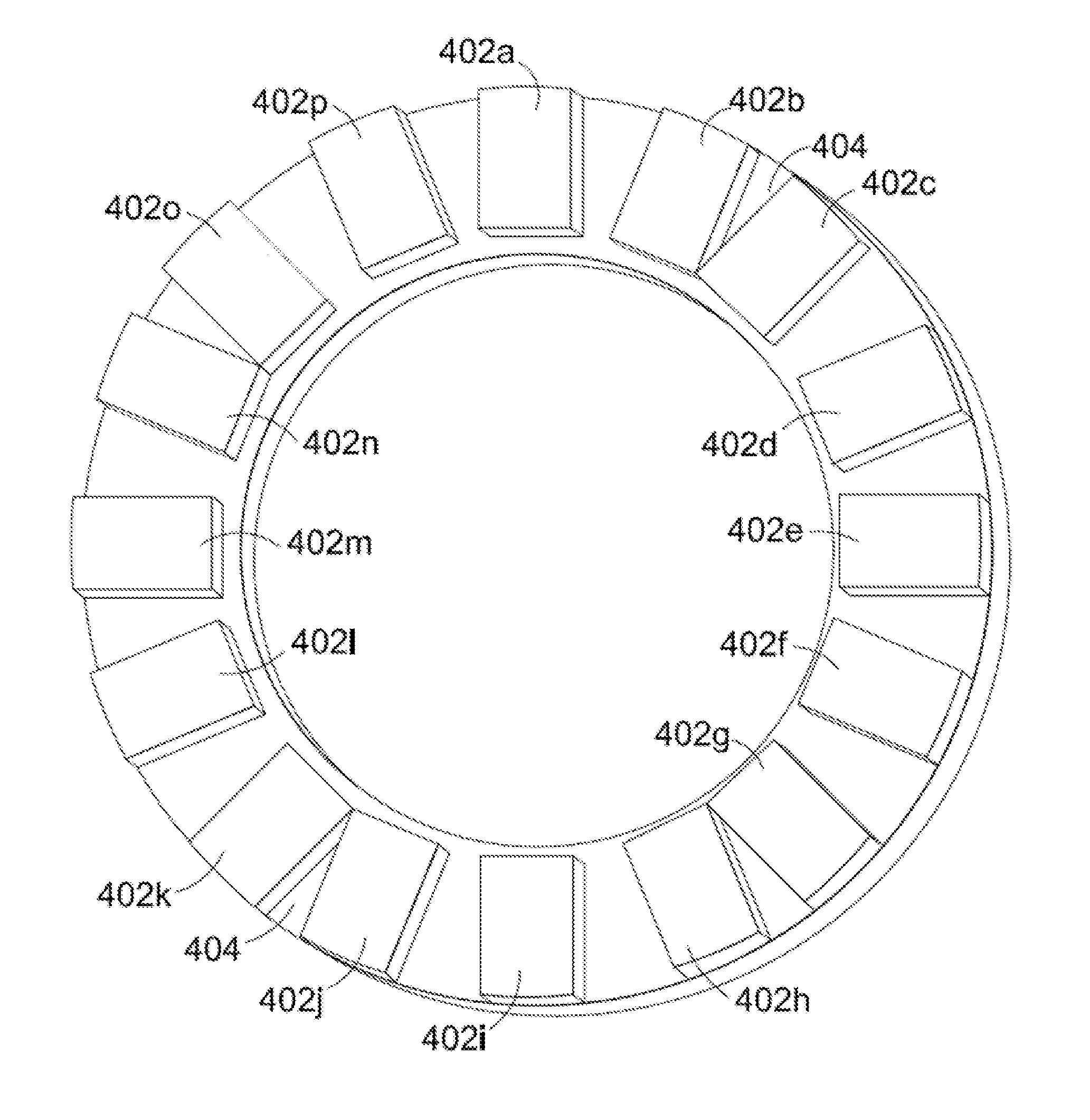
[0033]Referring to FIG. 4a this shows a first stage in design of an asymmetric rotor 400 according to an embodiment of the invention. In the illustrated example the rotor has 16 magnets 402 and is preferably employed with a stator having 24 poles. The magnets 402 are mounted on a backplate 404 which, in the illustrated example, has a ring shape. In general, however, the shape of the backplate is not critical and may depend, for example, on the driver arrangement from / to the rotor—in other arrangements, for example, the backplate 404 may be disc-shaped.

[0034]As illustrated in FIG. 4a the magnets 402 are arranged with alternating north 402a and south 402b pole faces and, at this stage in the design process, the magnets are spaced circumferentially at regular intervals around the backplate 404.

[0035]As illustrated in FIG. 4a the rotor has 8-fold symmetry. In FIG. 4b this symmetry has been broken by a pairwise displacement of the rotor magnets from their regularly spaced positions. In p...


PUM


Abstract

A rotor for an axial flux permanent magnet machine is described. The machine has a stator comprising a stator housing enclosing a set of coils wound on stator bars or teeth and disposed circumferentially at intervals about an axis on the machine, and a rotor bearing a set of permanent magnets and mounted for rotation about the said axis. The rotor and stator are spaced apart along said axis to define a gap therebetween in which magnet flux in the machine is generally in an axial direction. The magnets are disposed circumferentially around said rotor and define a plurality, n, of matching sets of magnets. Each set of magnets includes a plurality of magnets, wherein said n sets of magnets on said rotor have n-fold rotational symmetry. Within a said set, the magnets have different shapes and / or relative circumferential spacings of adjacent magnets within the set of magnets are irregular.

Description

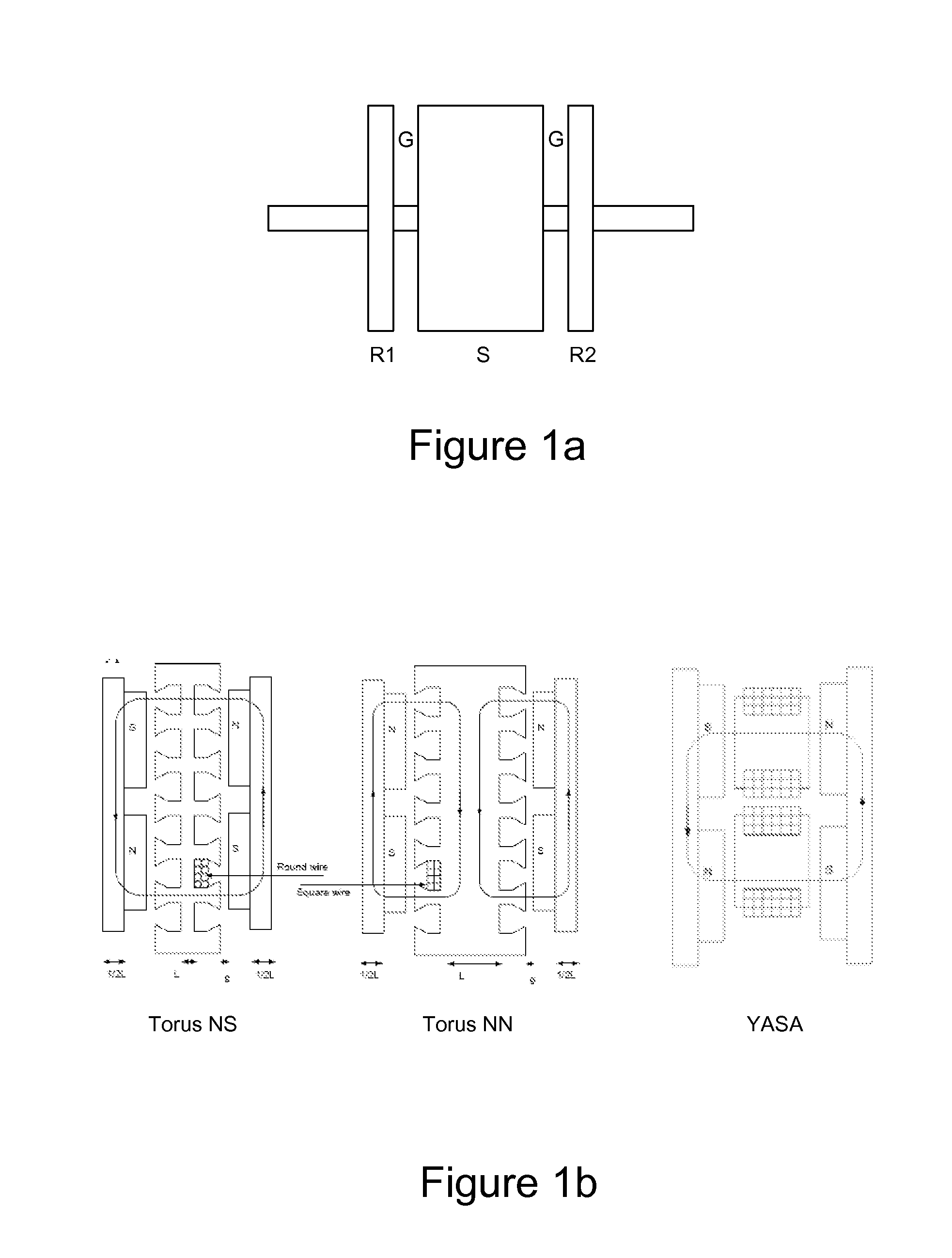
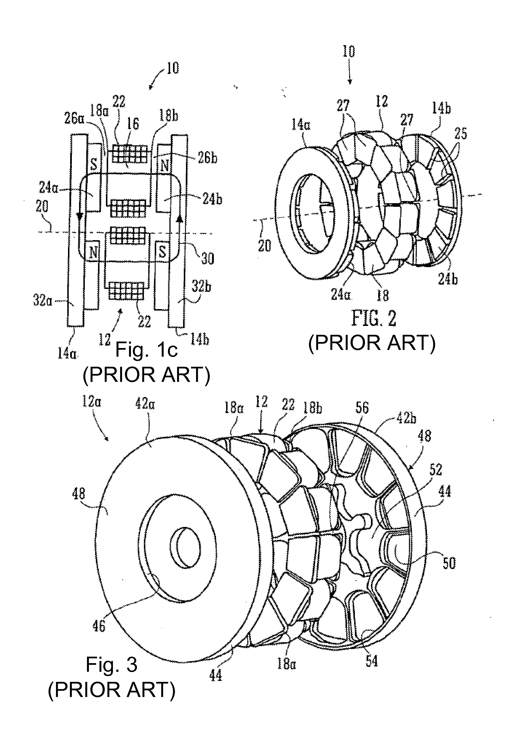
FIELD OF THE INVENTION[0001]This invention relates to techniques for reducing cogging, and for shaping the back emf, in axial flux permanent magnet machines.BACKGROUND TO THE INVENTION[0002]In this specification we are concerned with axial flux permanent magnet machines. Broadly speaking these have disc- or ring-shaped rotor and stator structures arranged about an axis. Typically the stator comprises a set of coils each parallel to the axis and the rotor bears a set of permanent magnets and is mounted on a bearing so that it can rotate about the axis driven by fields from the stator coils. FIG. 1a shows the general configuration of an axial flux machine with a pair of rotors R1, R2 to either side of a stator S—although a simple structure could omit one of the rotors. As can be seen there is an air gap G between a rotor and a stator and in an axial flux machine the direction of flux through the air gap is substantially axial.[0003]There are various configurations of axial flux perman...

Claims


Application Information

Patent Timeline
IPC IPC(8): H02K1/27H02K21/24
CPCH02K21/24H02K1/2793H02K29/03H02K1/2798
Inventor WOOLMER, TIM
Owner YASA LIMITED
Learn More