Electrical connector having strengthened members

Inactive Publication Date: 2006-05-18
HON HAI PRECISION IND CO LTD
View PDF10 Cites 14 Cited by
  • Summary
  • Abstract
  • Description
  • Claims
  • Application Information

AI Technical Summary

Benefits of technology

[0007] It is an object of the present invention to provide an electrical connector having strengthened members for strengthening the intensity of the insulative housing, and with smaller size and more convenient manufacture of the electrical connector.
[0008] In order to achieve the above-mentioned object, an electrical connector includes an insulative housing, a plurality of terminals retained in the insulative housing, a shell and a pair of strengthened members. The insulative housing comprises a base portion and a terminal supporting portion extending forwardly from the base portion. Each terminal has a contact portion extending along the terminal supporting portion. The shell is attached to the insulative housing and has a mating frame surrounding the contact portions and the terminal supporting portion to define a mating cavity therebetween. Strengthened members are buried at opposite ends of the terminal supporting portion. It could enhance the intensity of the insulative housing and improve the ability of enduring the deflected insertion of a complementary connector.

Problems solved by technology

However, a bare periphery of those contacts makes them vulnerable, then have poor orientation ability.
Therefore, when a complementary connector is inserted into the power connector, nevertheless the insertion direction has just a little deflection, those non-protective contacts would be forced and tend to warp even breaking off, which may result in signals shut off.
However, this structure complexes the manufacture of the housing, and does not follow the miniaturization trend of products.

Method used


Image

  • Electrical connector having strengthened members
  • Electrical connector having strengthened members
  • Electrical connector having strengthened members

Examples


Embodiment Construction

[0014] Reference will now be made to the drawing figures to describe the present invention in detail.

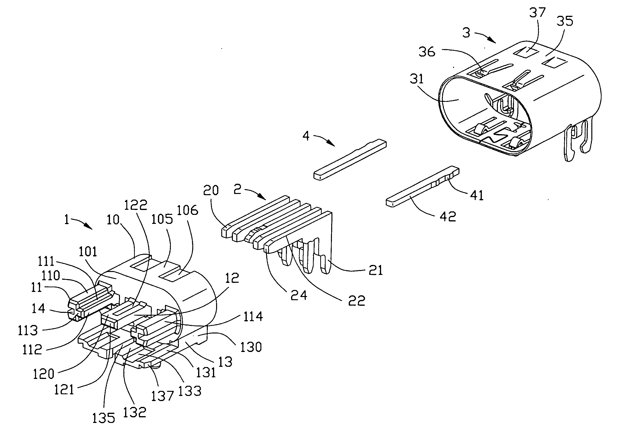
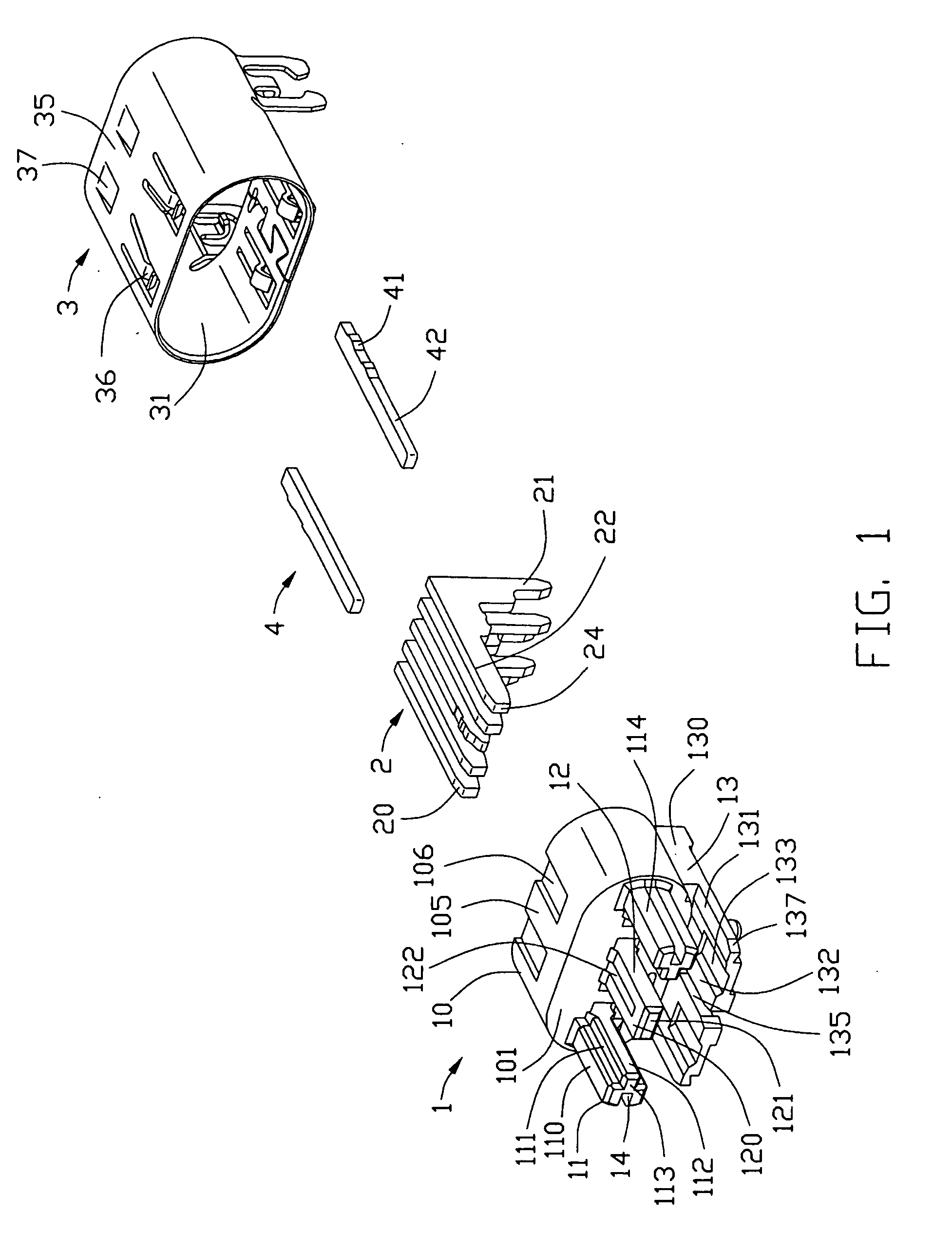
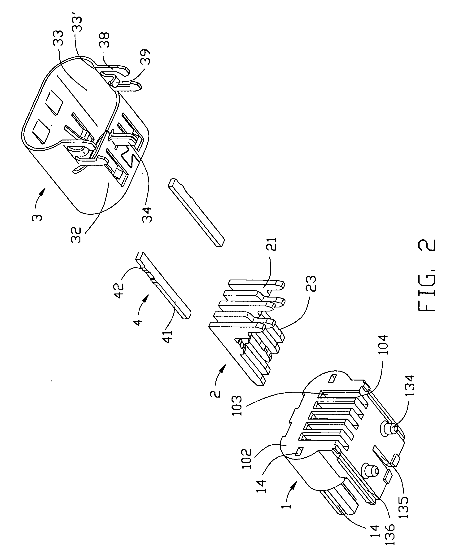
[0015] Referring to FIGS. 1-2, an electrical connector in accordance with the present invention comprises an insulative housing 1, a plurality of terminals 2 received in the insulative housing 1, a shell 3 surrounding the insulative housing 1 and a pair of strengthened members 4.

[0016] Taking reference to FIGS. 1-2, the insulative housing 1 has a base portion 10 with an approximately elliptic cross-section. The base portion 10 defines an upper face 105, a front face 101 and an opposite back face 102. A plurality of passageways 103 extend through the base portion 10 in a front-to-back direction. Several vertical slots 104 are defined by concaved into lower part of the back face 102, and are in communication with corresponding passageways 103 respectively. The base portion 10 defines two cutouts 106 on the upper face 105 thereof. A tongue portion 12 is formed by extending forwardly f...


PUM


Abstract

An electrical connector includes an insulative housing (1), a plurality of terminals (2) retained in the insulative housing, a shell (3) and a pair of strengthened members (4). The insulative housing comprises a base portion (10) and a terminal supporting portion (12) extending forwardly from the base portion. Each terminal has a contact portion (20) extending along the terminal supporting portion. The shell is attached to the insulative housing and has a mating frame (31) surrounding the contact portions and the terminal supporting portion to define a mating cavity therebetween. Strengthened members are buried at opposite ends of the terminal supporting portion.

Description

BACKGROUD OF THE INVENTION [0001] 1. Field of the Invention [0002] The present invention generally relates to an electrical connector, and particularly relates to an electrical connector having strengthened members for strengthening the intensity of the insulative housing. [0003] 2. Description of Related Arts [0004] Due to the booming development of the electronic industry, electro-consumer products become more and more popular. Miniaturization, integration and multi-function have been the inevitable trends what those products develop to. It also desires more power signals to be given to the electrical equipments, in respect that the integrated circuits have more applications, and the densities of the electrical components connected to the integrated circuits become much higher. To obtain more input power, power connectors of the electro-consumer products often need more conductors. U.S. Pat. No. 5,158,471 discloses a power connector having many contacts, which are densely arranged...

Claims


Application Information

Patent Timeline
IPC IPC(8): H01R13/648
CPCH01R13/6581
Inventor ZHANG, ZHI-QIANGWANG, NING
Owner HON HAI PRECISION IND CO LTD
Why Eureka
Try Eureka