Anti-Theft Security Panel For A Carrying Bag

Active Publication Date: 2015-08-20
TRAVEL CADDY
View PDF4 Cites 9 Cited by
  • Summary
  • Abstract
  • Description
  • Claims
  • Application Information

AI Technical Summary

Benefits of technology

The present invention provides a security panel assembly for bags and handbags that offers several technical benefits. Firstly, the wire matrix structure of the security panel assembly provides a plurality of closed wire shapes which are stable without the need for additional crimping, resulting in cost savings. Secondly, the wire matrix is smooth and continuous without any raised bumps that can cause discomfort to consumers and damage to the carrying bag. Thirdly, the uncoupled wire crossings in the wire matrix allow for flexibility and deformation while maintaining high cut-resistance, making it ideal for use in flexible bags designed for women. The interior security panel assembly includes foldable material layers and a wire mesh matrix, which can be stowed and attached to the bag in a secure and flexible manner. The handbag or carry strap formed by the invention is made of flexible fabric or a secure carry strap that can be easily detached and reattached. Overall, the invention offers a highly secure, priced and easy-to-assemble handbag construction that is resistant to snatching or cutting.

Problems solved by technology

On occasion, such bags are subject to theft or attempted theft.
While such constructions have potential applicability to handbags and other types of bags, they are difficult to assemble, can be bulky, rigid and inflexible, unattractive, and may not provide adequate security, particularly with respect to handbags that have carry straps and zippers associated therewith.
These prior art assemblies utilize a crimped wire mesh which not only is difficult and expensive to manufacture, but also has a comparatively stiff, expandable cage-like structure with very limited flexibility, rendering these types of assemblies unsuitable for many types of bags, such as handbags, purses, waist packs, and so on.
Such crimps are utilized to couple adjacent, non-crossing wires forming the mesh or cage-like structure, and in addition to creating unwanted stiffness and limiting movement of the wires, are also a potentially weak link in providing cut resistance, as such crimps may break, shear, or come off the mesh when subjected to cutting or pulling forces.
In addition, such crimps are often raised or protruding, thereby causing additional and unwanted wearing of the bag at these crimp locations.
As an additional result, the wire matrix not only provides the desired level of security, but also does not have the potential weak link of crimping.
The wire matrix, moreover, is smooth and continuous, without the raised bumps of the prior art which are palpable (and therefore undesirable by the consumer) and which cause unnecessary and undesirable wearing of the carrying bag.
Further, clasps on the zipper pulls or fastener pulls for the opening to the bag lock or attach to the bag so that access openings cannot be easily opened.
In this manner, the mounting pegs need not be fit into through openings in the second layer of material which translates to a decrease in assembly time for the security panel assembly herein.

Method used


Image

  • Anti-Theft Security Panel For A Carrying Bag
  • Anti-Theft Security Panel For A Carrying Bag
  • Anti-Theft Security Panel For A Carrying Bag

Examples


second embodiment

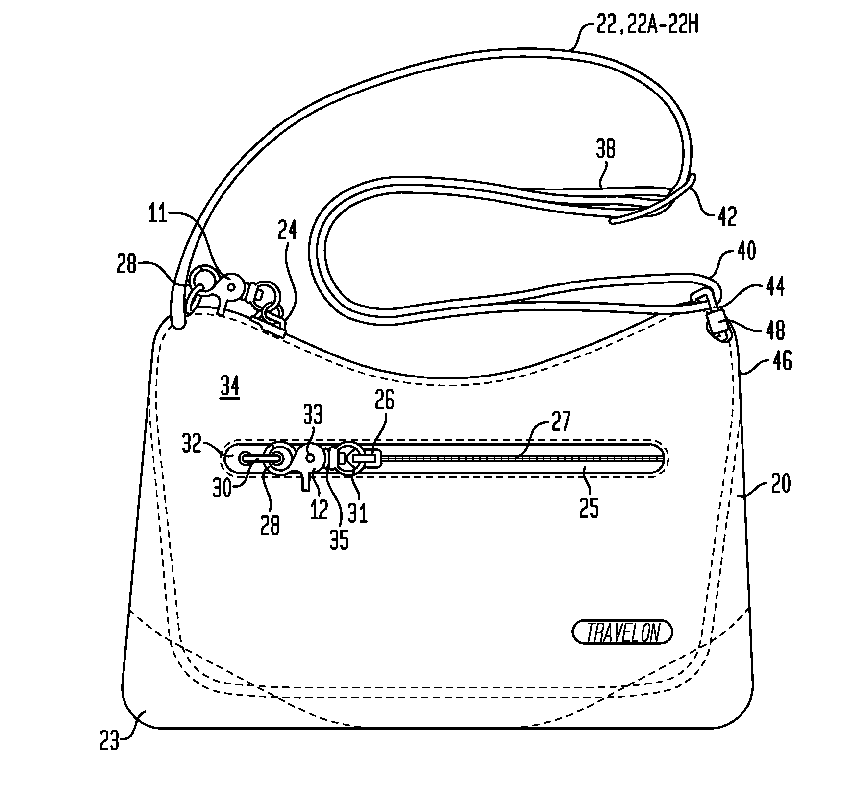
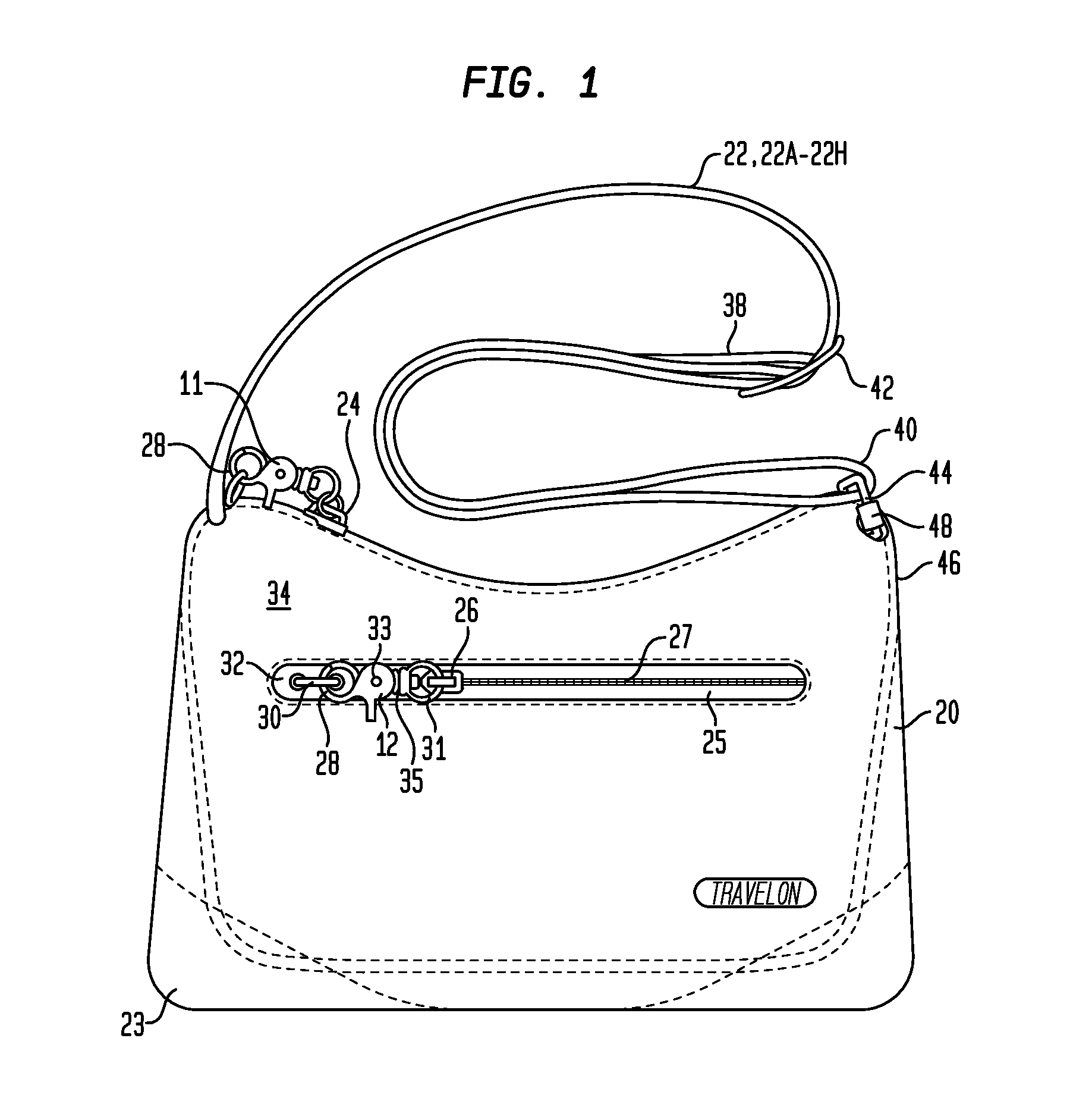
[0155]Not separately illustrated in FIGS. 1 and 19, those having skill in the art will recognize that the orientation of the clasp or fastener 11, 12 may also be reversed, namely, the clasp or fastener 11, 12 may be coupled to the exterior bag 23 and is releasably couplable to the zipper 24, 26, respectively. For example, loop 31 may be coupled or attached to the loop 30 which is attached to the outer layer 34 forming the exterior bag 23. The catch 28 may then be manually and releasably coupled to the zipper 24, 26, such as via a corresponding opening or hole in the zipper pull, instead of the illustrated loop 31, and again, a manual release operation of a clasp or fastener 11, 12 is required in order to enable operation of zippers 24, 26 to achieve access though zippered openings to the interior of the bag 20. such a second or secondary fastener 11A is illustrated and discussed below with reference to FIGS. 38, 38A and 38B.

[0156]Other types of secondary fasteners, in addition to cl...

first embodiment

[0167]FIG. 4A is cross-sectional view (through the A-A′ plane illustrated in FIG. 4) of a representative first embodiment of a carry strap 22, such as illustrated in FIGS. 1 and 4. As illustrated in FIGS. 1, 4 and 4A, a carry strap 22 generally comprises a first piece of flexible material (or webbing) 51, with a wire or cable 38 disposed longitudinally along the middle or center of the flexible material (or webbing) 51, illustrated as central region 562 located between first and second lateral regions 563, 564. The wire or cable 38 and central region 562 of the first flexible material are covered by a second piece of flexible material (or webbing) 49, also disposed longitudinally along the middle or center of the flexible material (or webbing) 51, and secured to the first piece of flexible material (or webbing) 51, such as through stitching 53, securing the wire or cable 38 in between the second flexible material 49 and the central region 562 of the first flexible material 51. As il...

fifth embodiment

[0185]FIG. 54 is an isometric view of a representative fifth embodiment of a carry strap 22D. As illustrated in FIG. 54, a single piece of webbing 561 is thicker in the middle (or central) region 562, allowing the first and second side or lateral regions 563, 564 to be wrapped around respective cables 38A, 38B and secured in place, as mentioned above, to form a carry strap 22D having a substantially even overall thickness and also generally a substantially thin form factor. Depending upon the comparative thickness of the middle (or central) region 562, as compared to the first and second side or lateral regions 563, 564, depending on the width of the first and second side or lateral regions 563, 564, and depending on the location of the placement of the wires or cables 38 along or within the first and second side or lateral regions 563, 564, various different configurations or arrangements of a carry strap 22D may result, as illustrated in FIGS. 55-57 and 61.

[0186]FIG. 55 is cross-s...


PUM

PropertyMeasurementUnit
Diameteraaaaaaaaaa
Lengthaaaaaaaaaa
Electrical resistanceaaaaaaaaaa

Abstract

In various embodiments, a carry (or carrying) bag is provided that includes an interior, substantially cut-resistant security panel assembly with a matrix of wires secured between or on one or more flexible material layers. Also in various embodiments, the security panel assembly may be positioned intermediate the bag outside wall and a lining of the bag, and in other embodiments, may also take the form of an expansion panel. Second or secondary locking fasteners are also provided to lock first or primary fasteners to or within the carrying bag, to provide security for compartments and pockets. A strap with one or more security cables, and various locking fasteners, may be attached to the carry bag. Methods for forming such security panel assemblies, expansion panels, and carrying straps are also disclosed.

Description

CROSS-REFERENCE TO RELATED APPLICATIONS[0001]This application is nonprovisional of and claims priority to and the benefit of U.S. Provisional Patent Application Ser. No. 61 / 949,452, filed Mar. 7, 2014, and further is a continuation-in-part of U.S. patent application Ser. No. 14 / 559,086, filed Dec. 3, 2014, which is a division of U.S. patent application Ser. No. 13 / 245,319, filed Sep. 26, 2011 and issued Jan. 6, 2015 as U.S. Pat. No. 8,925,181 B2, which is a continuation-in-part of prior International Application PCT / US10 / 028557, filed Mar. 24, 2010, which is a continuation-in-part of U.S. patent application Ser. No. 12 / 410,123, filed Mar. 24, 2009, which are commonly assigned herewith, the entire contents of which are incorporated herein by reference with the same full force and effect as if set forth in their entirety herein, and with priority claimed for all commonly disclosed subject matter.FIELD OF THE INVENTION[0002]This invention relates to various types of carrying bags and, ...

Claims


Application Information

Patent Timeline
IPC IPC(8): A45C3/00A45C13/18A45C13/10A45C3/06
CPCA45C3/06A45C13/103A45C13/18A45C13/185A45C13/20A45C13/30A45C2013/026A45C2013/306Y10T29/49Y10T29/5187A45C3/001
Inventor GODSHAW, DONALD E.HAI, DU
Owner TRAVEL CADDY
Why Eureka
Try Eureka