Fueling method for small, steady-state, aneutronic frc fusion reactors

a fusion reactor and steady-state technology, applied in nuclear reactors, nuclear engineering, greenhouse gas reduction, etc., to achieve the effects of promoting rapid loss of fusion products, less waste, and increasing the ion energy of plasma

Active Publication Date: 2015-08-13
THE TRUSTEES FOR PRINCETON UNIV
View PDF3 Cites 4 Cited by
  • Summary
  • Abstract
  • Description
  • Claims
  • Application Information

AI Technical Summary

Benefits of technology

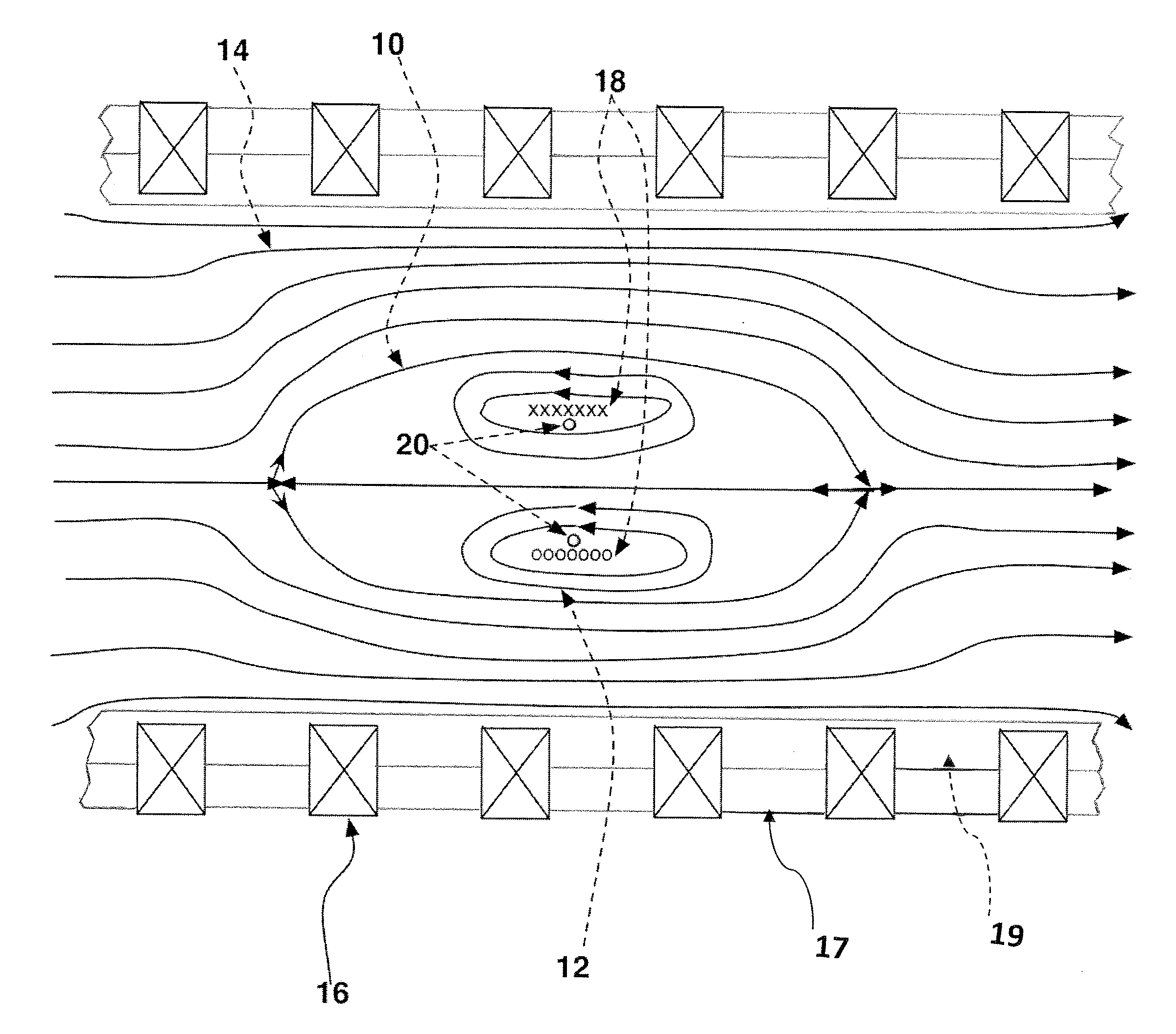
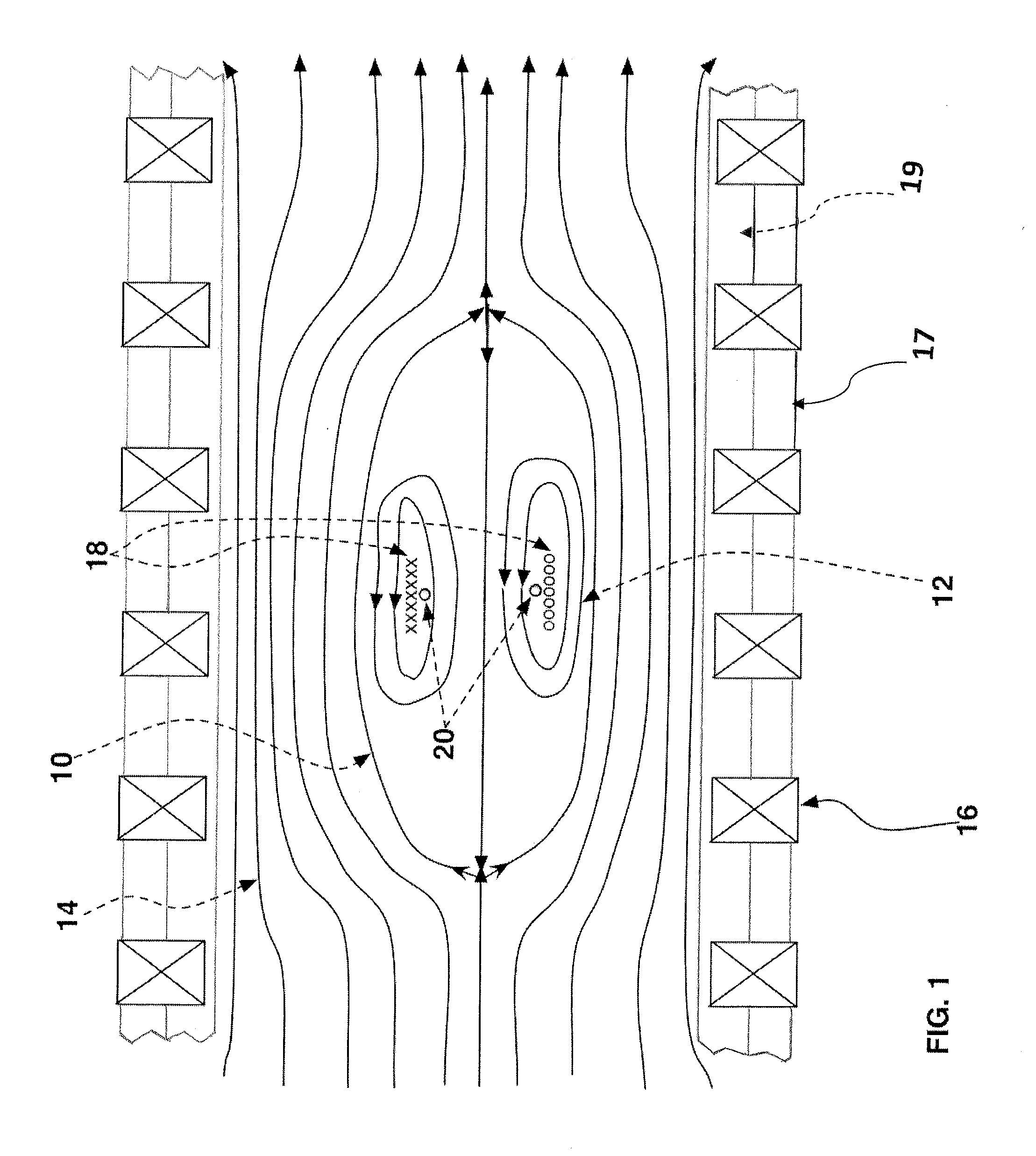
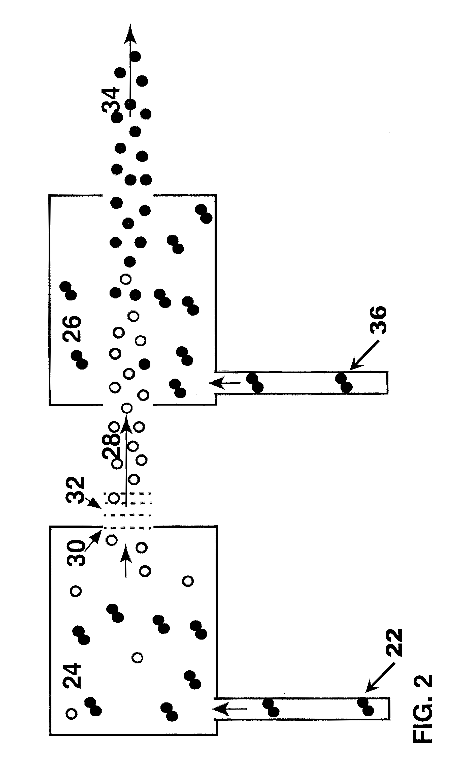
The present invention is a system and method for creating and injecting a beam of neutral ions into a plasma to fuel a continuous fusion reaction of deuterium and helium-3. This can lead to improved efficiency and control of fueling, with the ability to use rarer fuels and less of them. This is particularly useful for reactors located in aircraft and spacecraft where weight and fuel efficiency are critical.

Problems solved by technology

First, the primary claim thereof is the confinement of “gun”-produced FRC's between magnetic mirror coils and not fueling.

Method used


Image

  • Fueling method for small, steady-state, aneutronic frc fusion reactors
  • Fueling method for small, steady-state, aneutronic frc fusion reactors
  • Fueling method for small, steady-state, aneutronic frc fusion reactors

Examples


Embodiment Construction

[0020]In the following description, for purposes of explanation, specific numbers, materials and configurations are set forth in order to provide a thorough understanding of the invention. It will be apparent, however, to one having ordinary skill in the art, that the invention may be practiced without these specific details. In some instances, well-known features may be omitted or simplified so as not to obscure the disclosed scenarios. Furthermore, reference in the specification to “one embodiment” or “an embodiment” means that a particular feature, structure or characteristic described in connection with the embodiment is included in at least one embodiment of the invention. The appearances of the phrase “in an embodiment” in various places in the specification are not necessarily all referring to the same embodiment.

[0021]During the course of this description like numbers will be used to identify like elements according to the different views, which illustrate the invention.

[002...


PUM


Abstract

A system and method for fueling a fusion reactor. The system includes a reactor chamber containing a stable plasma including a fusion fuel; a heating system configured to heat the plasma and increase an ion energy of the plasma to a level sufficient for producing net power from fusion reactions in the stable plasma; a plurality of magnets coaxial to the reactor chamber, the plurality of magnets producing a magnetic field sufficient to confine the stable plasma and promote rapid loss of fusion products into a scrape off layer; and a neutral beam injection system configured to inject additional quantities of the fusion fuel to sustain the power output of the fusion reaction.

Description

CROSS REFERENCE TO RELATED APPLICATIONS[0001]This application claims the benefit of U.S. Provisional Patent Application Ser. No. 61 / 873,651, filed on Sep. 4, 2013. This application is a continuation-in-part of PCT / US2013 / 40520, filed May 10, 2013, which claims the benefit of U.S. Provisional Application Ser. No. 61 / 645,459, filed May 10, 2012, and U.S. patent application Ser. No. 14 / 466,425, filed Aug. 22, 2014, which claims the benefit of U.S. Provisional Application Serial No. 61 / 868,629, filed Aug. 22, 2013. The contents of each of these applications are incorporated herein by reference.STATEMENT REGARDING FEDERALLY SPONSORED RESEARCH OR DEVELOPMENT[0002]This invention was made with government support under Grant #DE-ACO2-09CH11466 awarded by the Department of Energy. The government has certain rights in this invention.FIELD OF THE INVENTION[0003]The present invention relates generally to the field of plasma physics and, in particular, to methods and apparati for introducing fuel...

Claims


Application Information

Patent Timeline
Patent Type & Authority Applications(United States)
IPC IPC(8): G21K1/14H05H1/02
CPCH05H1/02G21K1/14G21B1/052G21B1/15Y02E30/10
Inventor COHEN, SAMUEL A.STOTLER, DARENBUTTOLPH, MICHAEL
Owner THE TRUSTEES FOR PRINCETON UNIV
Why Eureka
Try Eureka