
Electrokinetic Process And Apparatus For Consolidation Of Oil Sands Tailings

a technology of electrokinetic process and oil sands tailings, which is applied in the direction of chemistry apparatus and processes, waste water treatment from quaries, waste water treatment from gaseous effluents, etc., can solve the problem of virtually inability to release pore water pressure by conventional means, and achieve the effect of increasing the capacity of the tailings pond and freeing up the pond spa

Active Publication Date: 2015-08-13
ELECTRO KINETIC SOLUTIONS
View PDF1 Cites 2 Cited by
  • Summary
  • Abstract
  • Description
  • Claims
  • Application Information

AI Technical Summary

Benefits of technology

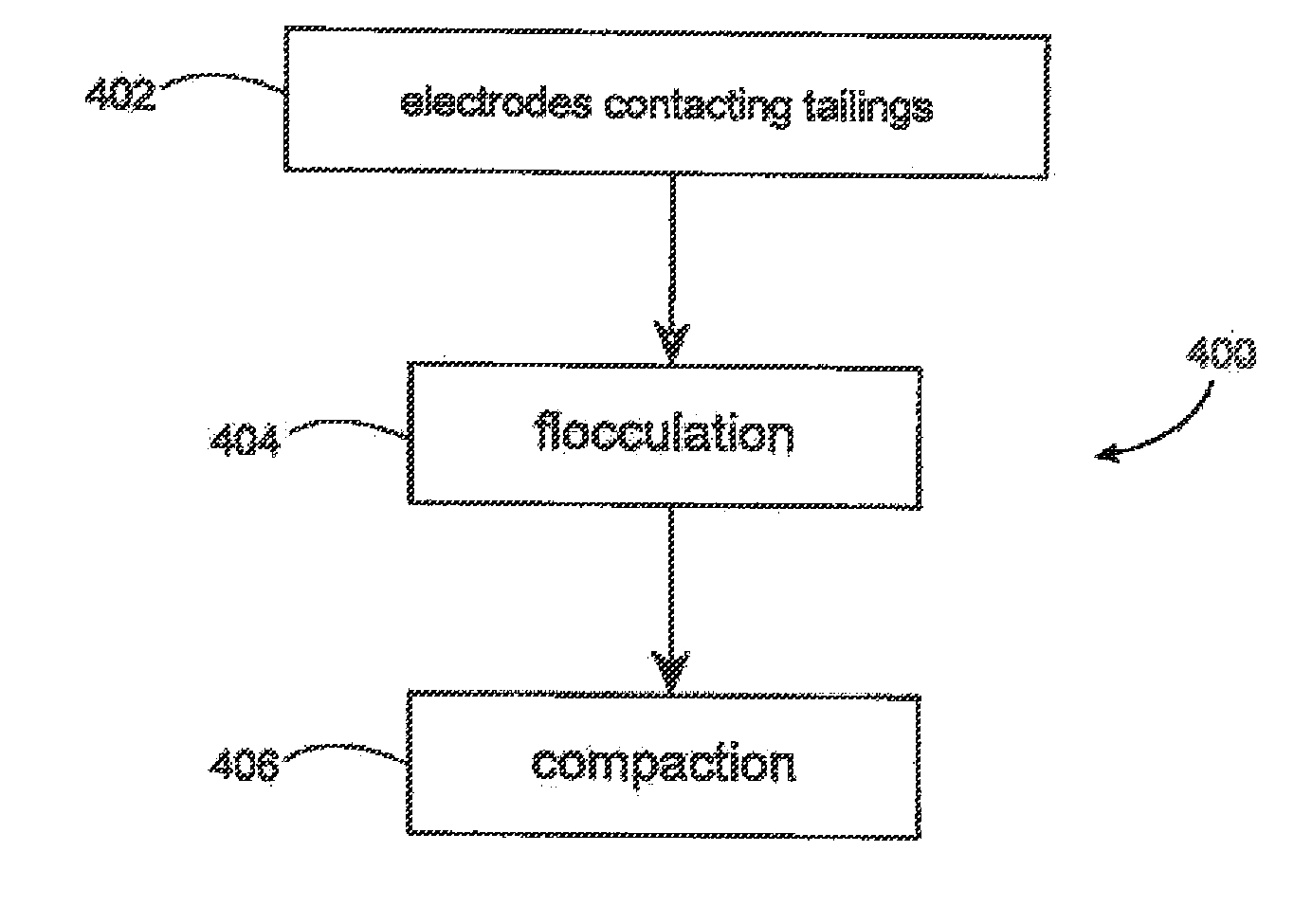
[0021]These phases include the initial water release under the influence of an electric field in a flocculation step with an accompanying release of water, followed or contemporaneously occurring with the secondary release of pore water during the electro-osmotic flow of low pH water produced at the anode which when electro-osmotically transported through the MFT / FFT neutralizes the diffuse double layer. This results in the release of ions from the pores which are transported to the anode and cathode via electrophoresis, electromigration and electro-osmosis. With the ions released and transported to the anode and cathode, the electrical resistance of the wet tailings increases, which allows the application of higher voltage gradients at lower current draw, or improved energy efficiency to achieve compaction through electrostriction. As a result, in one embodiment, the electrokinetic remediation process involves two distinct and separate steps involving the water release / ion release / flocculation, followed by compaction through electrostriction as the electrical resistance increases. The draining of water from the tailings also increases the electrical resistance and provides a means of controlling the process.

Problems solved by technology

MFT / FFT, in its original state being a thixotropic liquid cannot support a load, and given that the liquid is stored in large ponds, there is virtually no ability to release pore water pressure by conventional means, such as compressive loading.

Method used


Image

  • Electrokinetic Process And Apparatus For Consolidation Of Oil Sands Tailings
  • Electrokinetic Process And Apparatus For Consolidation Of Oil Sands Tailings
  • Electrokinetic Process And Apparatus For Consolidation Of Oil Sands Tailings

Examples


Embodiment Construction

[0052]In this specification the terms MFT, or MFT / FFT or FFT shall mean the tailings that exist in tailings ponds that arise from the extraction of hydrocarbons, such as bitumen, from tar or oil sands, or fly ash tailings ponds. As will be appreciated by those skilled in the art, the exact composition of MFT / FFT will vary, depending upon the composition of the ore being mined due to local variations in such ore. However, as used herein the term is intended to include compositions of material that include water, clays, silts, and residual hydrocarbons and hydrocarbon by-products among other things.

[0053]The application of an electrical field to a dielectric material results in certain electro-kinetic phenomena, including electro-osmosis, the movement of water from an anode to a cathode; electrophoresis, the movement of ions in the water to oppositely charged electrodes, and electrostriction, a result of the application of an electrical field that results in mechanical work which defo...


PUM

PropertyMeasurementUnit
load bearing capacityaaaaaaaaaa
bearing capacityaaaaaaaaaa

Abstract

A method is provided of treating liquid tailings using electro-kinetics by creating a variable voltage between two electrodes in the tailings. Flocculation and water release from the tailings is induced by establishing an electrical field between the two electrodes. The electrodes are connected to an electrical power source having the variable voltage to create a cathode and an anode. Compacting the flocculation solids and removing further water released from the compacting solids allows for the creation of a compacted material having a desired load bearing capacity.

Description

FIELD OF THE INVENTION[0001]This invention relates generally to the broad field of pollution control. More particularly, this invention relates to methods and apparatus that can be used to mitigate the persistent nature of certain types of tailings ponds, such as tailings ponds filled with waste products from tar or oil sand recovery processes. Such mitigation allows land reclamation to occur.BACKGROUND OF THE INVENTION[0002]Oil or tar sands are a source of bitumen, which can be reformed into a synthetic crude or syncrude. At present a large amount of hydrocarbon is recovered through surface mining. To obtain syncrude, the hydrocarbons must be first separated from the sand base in which it is found. This sand based material includes sands, clays, silts, minerals and other materials. The most common separation first step used on surface mined tar sands is the hot water separation process which uses hot water to separate out the hydrocarbons. However, the separation is not perfect and...

Claims


Application Information

Patent Timeline
Patent Type & Authority Applications(United States)
IPC IPC(8): C02F1/463C02F11/125C02F11/15
CPCC02F1/463C02F2201/46135C02F2103/10C02F1/52C02F11/006C02F11/125C02F2103/18C02F11/15
Inventor SMITH, GREGORY J.BEATTIE, BRUCE S.PARROTT, ROBERT C.MICAK, JAMESGARCIA, PAULKIMZEY, DOUGKROLL, JR., THOMAS M.
Owner ELECTRO KINETIC SOLUTIONS
Learn More