Providing a Spatial Anatomical Model of a Body Part of a Patient

Active Publication Date: 2015-07-30
SIEMENS HEALTHCARE GMBH
View PDF8 Cites 8 Cited by
  • Summary
  • Abstract
  • Description
  • Claims
  • Application Information

AI Technical Summary

Benefits of technology

The present invention relates to a system and method for creating a patient-specific three-dimensional model of a body part (e.g. heart) using different modalities of imaging examinations. The system includes a control device and output device that form a telemedical system, allowing for remote communication of the model. The model is created by using a high-quality model of the body part, which offers the possibility of viewing the body part from different perspectives and on different planes. The model can be used for planning operations or outputting a template for the body part. The invention allows for improved clarity and accuracy of the model, and reduces the need for multiple digital representations of the patient. The model also has a high information content, enabling the user to simulate a medical procedure and to store control signals for subsequent operations.

Problems solved by technology

The visualization of a complex anatomical region (e.g., a part of the body such as a subregion of a vascular system or of an organ) is becoming more and more detailed and more complex as a result of state-of-the-art imaging methods.
The advent of superpositioning methods (e.g., overlaying of a two-dimensional (“2D”) image with a three-dimensional (“3D”) image, insertion of lines and structures that represent a medical apparatus such as a stent, or an ostial branch, or “optimal next projection”) has led to images becoming overloaded to such an extent that it becomes increasingly difficult for a user to extract essential information from the image.
This entails the risk that, for example, minute anatomical changes or abnormalities of the body part will be overlooked.
As a result, the user quickly loses sight of what is essential.
However, there continues to exist in this situation the disadvantage that an image or a holographic projection quickly becomes overloaded with information, and certain information is difficult to recognize and gets overlooked.
This is detrimental, for example, in the case of telemedical applications, since only overloaded images are available to a physician located far from the place of examination of the patient.

Method used


Image

  • Providing a Spatial Anatomical Model of a Body Part of a Patient
  • Providing a Spatial Anatomical Model of a Body Part of a Patient

Examples


Embodiment Construction

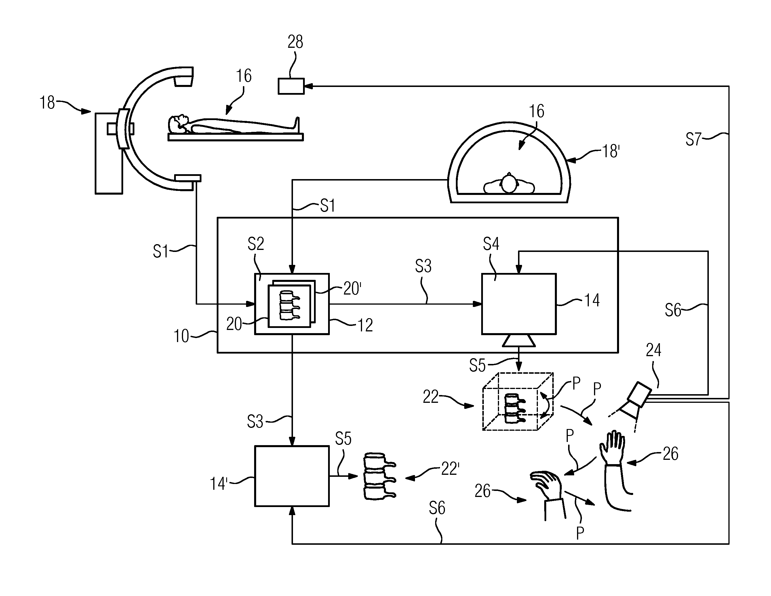
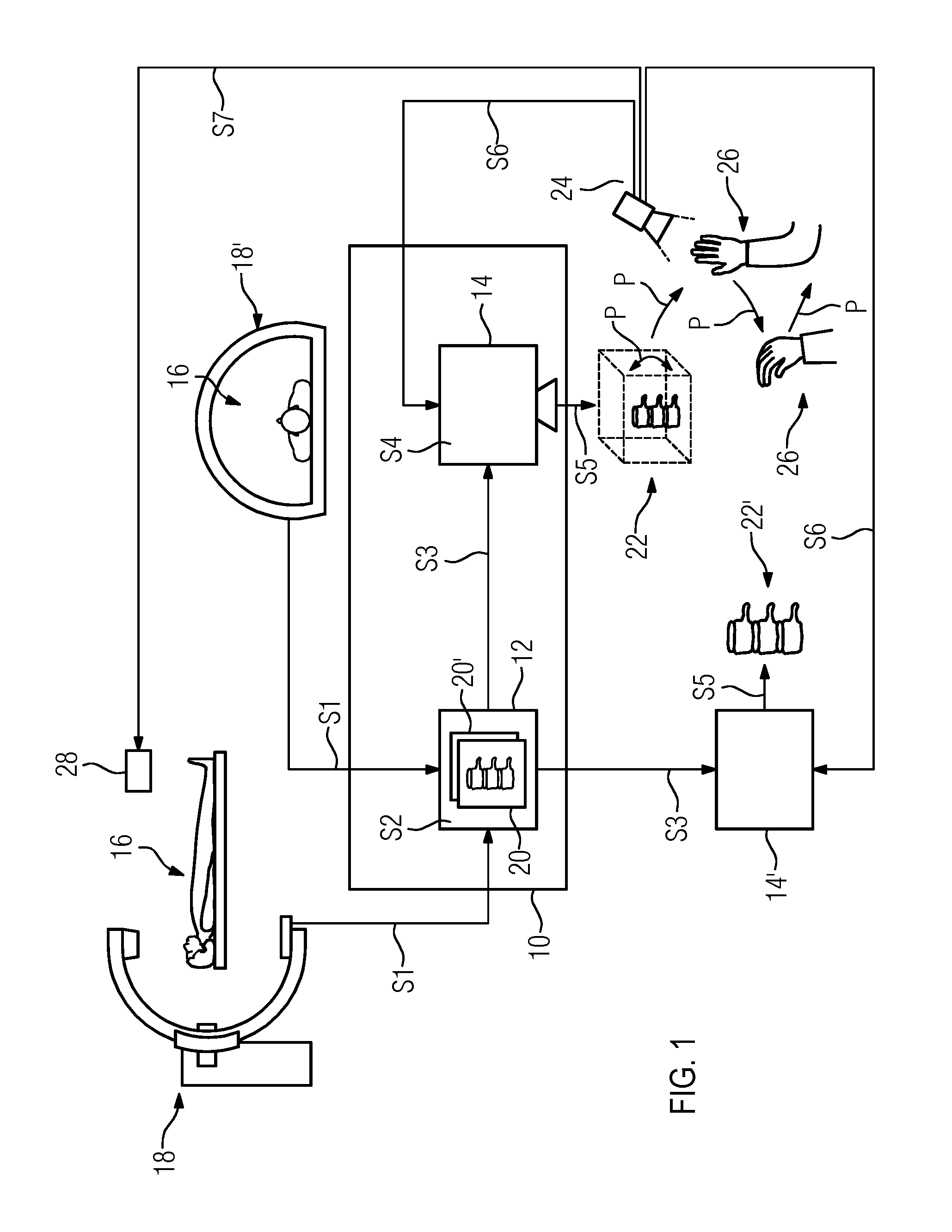
[0027]FIG. 1 shows a telemedical system 10 including a control device 12 and an output device 14. In this arrangement, the control device 12 includes, for example, a microchip or a control unit.

[0028]The output device 14 is embodied, for example, as a display composed of a polymer material, as an apparatus for representing a hologram on a holographic film by a laser, or as an apparatus enabling the generative manufacture of a workpiece. In one embodiment, the output device 14 includes an apparatus enabling the generative manufacture of a workpiece, such as, for example, a 3D printer for laser melting, electron beam melting, selective laser sintering, stereolithography or for “digital light processing”, polyjet modeling or “fused deposition modeling”. Further exemplary apparatuses for the generative manufacture of a workpiece include, for example, an apparatus for rapid prototyping, rapid tooling or rapid manufacturing.

[0029]In the telemedical system 10, the control device 12 and the...


PUM


Abstract

A method for providing a spatial anatomical model of a body part with the aid of at least one imaging examination modality is provided. At least one digital representation of the at least partial body part is provided to a control device by the at least one imaging examination modality. Based on the at least one digital representation, the control device determines a digital model and transmits the digital model to an output device. The output device determines the spatial model and outputs the spatial model as a hologram or workpiece. The spatial model is determined as a function of at least one specifying control parameter that describes a relevant portion of the spatial model and / or a mode of representation of the spatial model and / or of the portion. The control parameter is determined based on an operator control action executed by a user and received by an operator control device.

Description

[0001]This application claims the benefit of DE 10 2014 200 915.4, filed on Jan. 20, 2014, which is hereby incorporated by reference in its entirety.BACKGROUND[0002]The present embodiments relate to providing a spatial anatomical model of a body part of an animal or human patient with the aid of an imaging examination modality.[0003]The visualization of a complex anatomical region (e.g., a part of the body such as a subregion of a vascular system or of an organ) is becoming more and more detailed and more complex as a result of state-of-the-art imaging methods. The advent of superpositioning methods (e.g., overlaying of a two-dimensional (“2D”) image with a three-dimensional (“3D”) image, insertion of lines and structures that represent a medical apparatus such as a stent, or an ostial branch, or “optimal next projection”) has led to images becoming overloaded to such an extent that it becomes increasingly difficult for a user to extract essential information from the image. This en...

Claims


Application Information

Patent Timeline
IPC IPC(8): G06T17/20G06T19/20
CPCG06T17/20G06T2207/30004G06T2219/2004G06T19/20A61B5/745A61B6/032A61B6/4441A61B6/5211A61B8/00G06T19/00G16H50/20
Inventor SIEBARTH, KERSTIN ALEXANDRAWIETS, MICHAEL
Owner SIEMENS HEALTHCARE GMBH
Why Eureka
Try Eureka