Flow uniformity of air-cooled battery packs

Active Publication Date: 2015-07-30
GM GLOBAL TECH OPERATIONS LLC
View PDF2 Cites 15 Cited by
  • Summary
  • Abstract
  • Description
  • Claims
  • Application Information

AI Technical Summary

Benefits of technology

The present invention relates to a system for improving the cooling of battery cells in a battery assembly. The invention involves the modification of the surface of an air flow plenum or manifold to increase the inlet pressure of the first few channels at each battery module. This is achieved by adding beads or related undulations to the plenum to promote a more equitable distribution of cooling fluid pressures. By doing so, the beads increase local cross sectional area, which in turn increases the pressure. This high pressure helps to improve the uniformity of the flow rate of the individual cooling channels. The invention also includes a battery pack assembly made up of numerous battery cells arranged in modular format, with cooling channels defined between adjacent cells within each module and between adjacent modules. The system further includes components configured to deliver cooling fluid to the various cells and modules within the pack, such as a plenum, conduit, manifold or related duct that is placed in fluid communication with the channels that are formed between adjacent cells with each module. The strategic placement of the beads promotes a more equitable distribution of the cooling fluid between the various inter-module and intra-module cooling channels.

Problems solved by technology

Left unchecked, this excess built-up heat may damage the cells and impact their operation.
While such an approach has the virtue of providing a relatively unimpeded air flow path to all of the cells that are contiguous with the plenum, the potential exists for significant air flow (and concomitant temperature) non-uniformity among the individual battery cells; much of this is due to uneven pressure drops between the channels formed between adjacent cells or cooling plates as the air goes from the inlet plenum of the battery pack to the outlet plenum.
This problem is particularly significant in situations where there is a large distance between the last channel of a fluidly upstream battery module and the first channel of an adjacent downstream module; where this distance is larger than the distance between adjacent channels within the same module, the resulting pressure difference is such that the driving force (and resulting flow) in and around the first channel of each battery module is significantly reduced relative to its more closely-aligned intra-module channels.

Method used


Image

  • Flow uniformity of air-cooled battery packs
  • Flow uniformity of air-cooled battery packs
  • Flow uniformity of air-cooled battery packs

Examples


Embodiment Construction

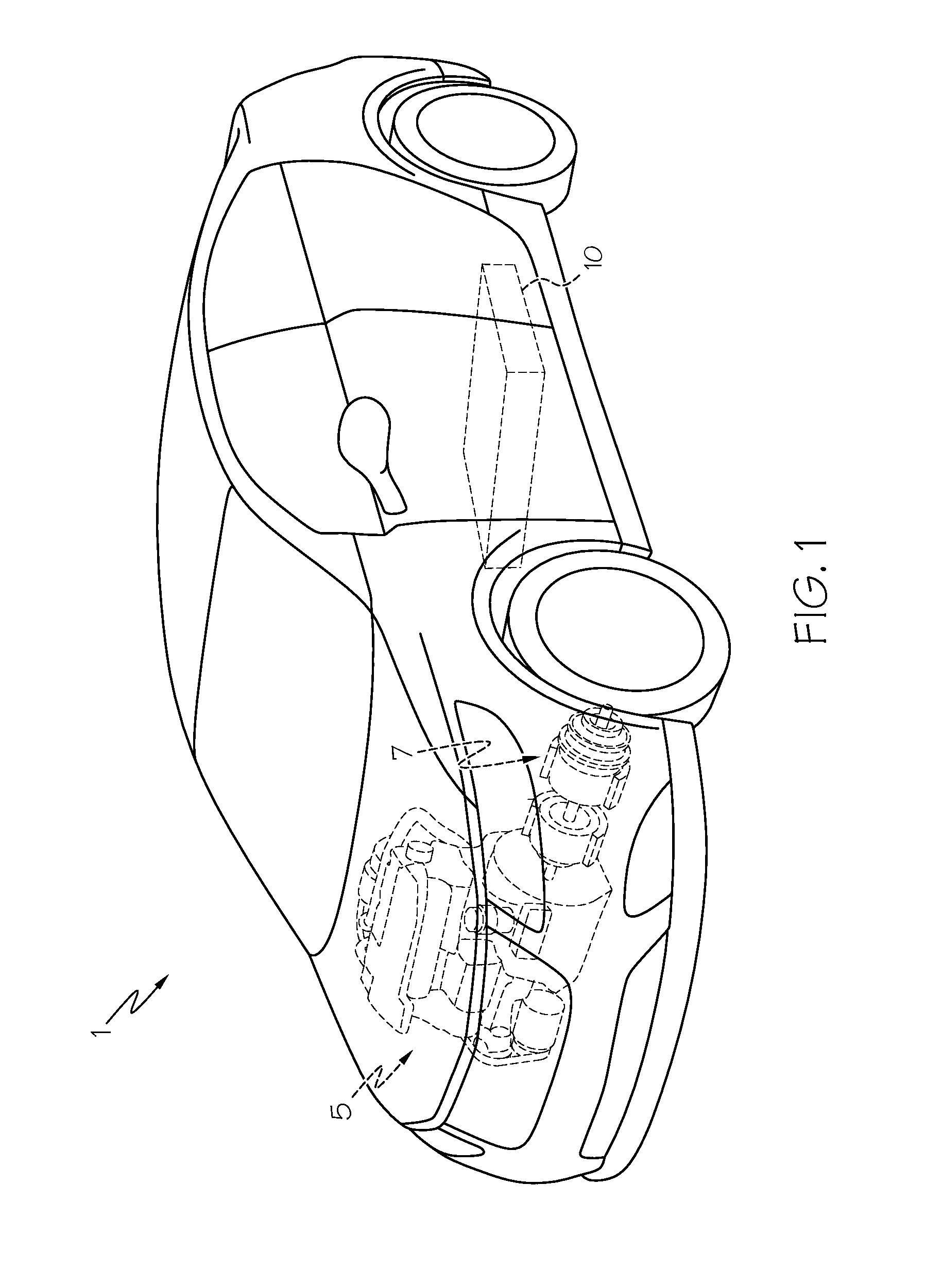
[0018]Referring first to FIG. 1, a vehicle 1 includes a hybrid propulsion system in the form of an electric power source made up of a conventional ICE 5 and a battery pack 10. Such a vehicle is known as a hybrid electric vehicle (HEV). It will be appreciated by those skilled in the art that vehicle 1 may not require an ICE 5, in such case, rather than being an HEV, it is an electric vehicle (EV); either form is within the scope of the present invention. An electric motor 7 may be coupled to one or both of the ICE 5 and battery pack 10 to provide traction to the wheels. Additional drivetrain components (none of which are shown) useful in providing propulsive power to one or more of the wheels and coupled to one or both of the battery pack 10 and ICE 5 are understood to include rotating shafts, axles, transmission, controllers or the like. While vehicle 1 is presently shown as a car, the applicability of the hybrid propulsion system to other such automotive forms (including trucks, bu...


PUM


Abstract

A battery pack and method of cooling a battery pack. In one form, the battery pack is an assembly made up of numerous battery cells arranged within numerous modules. Cooling channels that receive cooling fluid from a ducted supply are placed between adjacent cells or cooling plates within each of the modules. The ducted supply includes beads or related area-increasing undulations that are designed to improve both the stiffness of the ducting as well as the uniformity of the flow rates of individual cooling channels within each of the modules. In one form, the pressure-enhancing beads are placed in an inlet portion of the ducting that is adjacent a forward portion of one or more of the sequentially-encountered modules in order to promote a more equitable distribution of the cooling fluid between the various cooling channels within each of the modules.

Description

BACKGROUND OF THE INVENTION[0001]This invention relates generally to an improved air-cooled battery pack with a plurality of battery cells that are used to generate motive power for vehicular and related transportation applications, and more particularly to varying the air flow amongst the individual battery cells within a battery cell module or pack such that the flow depends on each battery's position within the respective module or pack.[0002]Various batteries, including lithium-ion, lead acid and nickel-metal hydride variants, may be configured to supplement or supplant conventional internal combustion engines (ICEs) for automotive and related transportation applications. The ability to passively store energy from stationary and portable sources, as well as from recaptured kinetic energy provided by the vehicle and its components, makes batteries (in general) and rechargeable batteries (in particular) ideal to serve as part of a propulsion system for cars, trucks, buses, motorcy...

Claims


Application Information

Patent Timeline
IPC IPC(8): B60L11/18
CPCY10S903/907B60L11/1874B60L58/26B60L2240/545Y02E60/10Y02T10/70B60L3/0046H01M10/60H01M10/613H01M10/625H01M10/65
Inventor SUN, HONGGUANGDIXON, REGAN P.
Owner GM GLOBAL TECH OPERATIONS LLC
Why Eureka
Try Eureka