
Polymer Mixer

a technology of polymer mixer and impeller, which is applied in the direction of mixing, rotary stirring mixer, transportation and packaging, etc., can solve the problems of uncoiled molecules becoming shear sensitive, and achieve the effects of high shear mixing energy, high velocity and turbulen

Inactive Publication Date: 2015-07-30
PROMINENT FLUID CONTROLS
View PDF9 Cites 3 Cited by
  • Summary
  • Abstract
  • Description
  • Claims
  • Application Information

AI Technical Summary

Benefits of technology

This patent describes a device called a polymer mixing impeller that helps to mix and recirculate viscous maturing solution with lower energy to prevent damage. The device includes discs that move the solution in a way that prevents shearing. Additionally, the patent also describes a valve that helps to discharge the polymer in a thin layer, maximizing contact with the water.

Problems solved by technology

The uncoiled molecules become shear sensitive and can be damaged by further high shear mixing energy.

Method used


Image

  • Polymer Mixer
  • Polymer Mixer
  • Polymer Mixer

Examples


Embodiment Construction

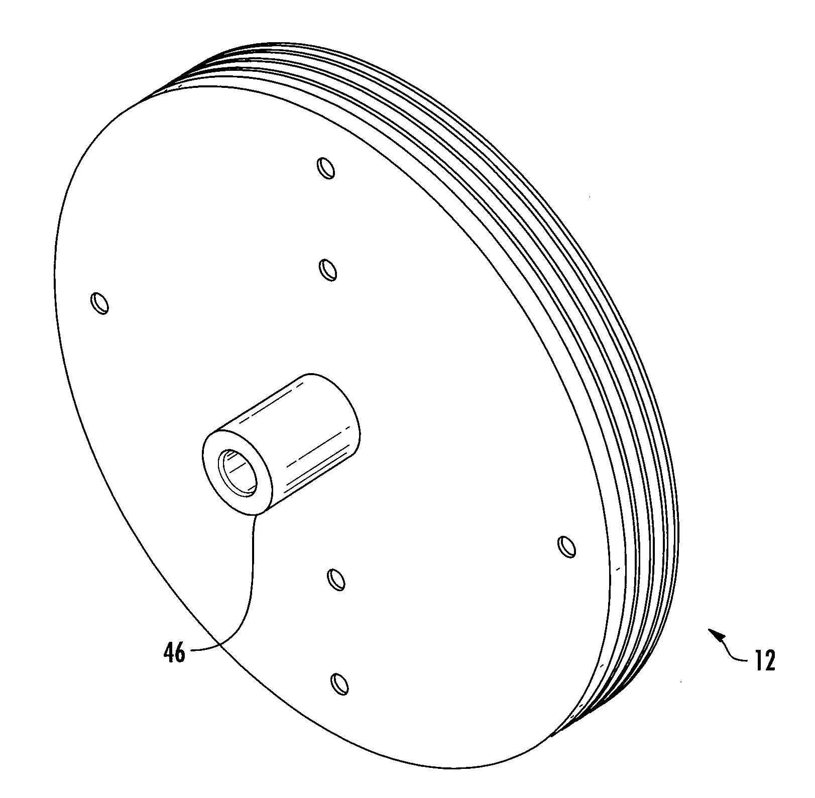
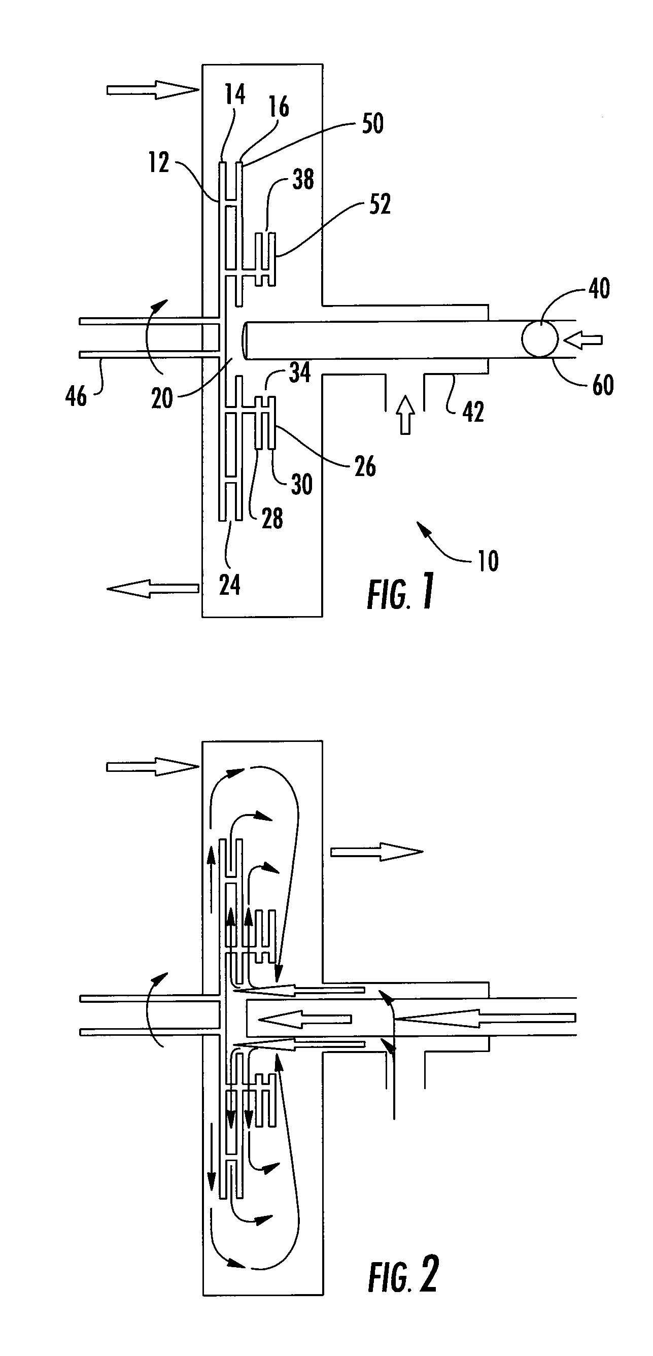
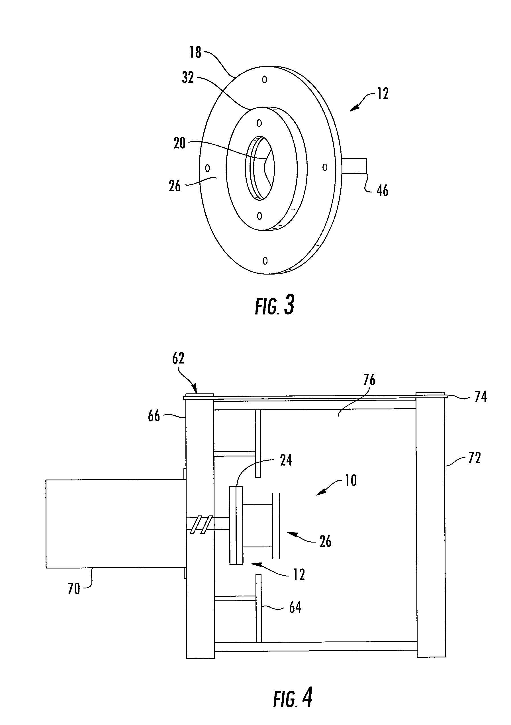
[0027]Referring now to the Figures, disclosed is a polymer mixing impeller 10 capable of providing a high shear initial mixing energy. The polymer mixer has a high shear member 12 constructed from two spaced apart circular primary discs 14, 16 having an outer diameter 18 and a first inlet 20 formed along an inner diameter 22 with a high shear chamber 24 formed therebetween. A low shear member 26 is constructed from two spaced apart circular secondary discs 28, 30 having an outer diameter 32 and a second inlet 34 formed along an inner diameter of the secondary disc with a low shear chamber 38 formed therebetween. A first injection pipe 40 is used for introducing polymer into the first inlet 20 of the primary discs 14, 16. A second injection pipe 42 is used for introducing dilution water into the first inlet of 20 of the primary discs 14, 16. A drive shaft 46 is coupled to the high shear member 12 and low shear member 26 for rotation. The injection of polymer and dilution water into t...


PUM

PropertyMeasurementUnit
velocity speedaaaaaaaaaa
speedaaaaaaaaaa

Abstract

A polymer mixer comprising an impeller formed from a series of rotating discs mounted to a drive shaft and driven by an electric motor. Polymer is piped through a mixing chamber to the inlet of the rotating discs that creates a high shear mixing zone. Dilution water is also piped to the high shear mixing zone which is a concentric hole in the center of the discs which serves as a liquid inlet when the discs are spinning. The discs are in close proximity creating high velocity and turbulence via centrifugal force. An open design between the discs allows the disc surface to pass the solution molecules multiple times before the molecules exit the perimeter, creating a shearing affect by the high speed surface in the solution. Discs of smaller diameter are coupled to the high shear discs to further mix and recirculate more viscous solutions.

Description

PRIORITY CLAIM[0001]In accordance with 37 C.F.R. 1.76, a claim of priority is included in an Application Data Sheet filed concurrently herewith. Accordingly, the present invention claims priority to U.S. Provisional Patent Application No. 61 / 931,972, entitled “POLYMER MIXER”, filed Jan. 27, 2014. The contents of the above referenced application is incorporated herein by reference.FIELD OF THE INVENTION[0002]This invention is related to the field of mixing devices and in particular to a polymer mixer impeller.BACKGROUND OF THE INVENTION[0003]Water soluble polymers are used industry wide to aid in water / solids separation processes. Polymers are long chain carbon-carbon molecules bonded to various functional groups to provide charge sites along the length of the polymer chain. These charge sites attract and hold small particles of opposite charge, combining them into a much larger particle. This process is known as flocculation wherein the aggregation of dispersed and colloidal matter ...

Claims


Application Information

Patent Timeline
Patent Type & Authority Applications(United States)
IPC IPC(8): B01F7/00B01F3/08B01F15/00
CPCB01F7/00491B01F15/00538B01F2003/0884B01F2215/0049B01F2003/0896B01F3/0857B01F2215/0481B29B7/40B29B7/402B29B7/385B01F23/431B01F23/483B01F27/1155B01F35/5311B01F2101/2805
Inventor MORRISON, RALPH LEAVELLESEIFERT, GLEN JOHNSTRACK, JOHN M.THOMAS, EDWARD J.
Owner PROMINENT FLUID CONTROLS
Learn More