
Methods and apparatus for envelope tracking system

a tracking system and envelope technology, applied in the field of methods and apparatus for envelope tracking systems, can solve the problems of poor power amplifier efficiency, low dc to rf power conversion efficiency of operation, and inability to carry (subscriber) wireless communication units, etc., to achieve the effect of alleviating one or two, and reducing the number o

Active Publication Date: 2015-07-09
MEDIATEK INC
View PDF1 Cites 34 Cited by
  • Summary
  • Abstract
  • Description
  • Claims
  • Application Information

AI Technical Summary

Benefits of technology

[0019]Accordingly, the invention seeks to mitigate, alleviate or eliminate one or more of the above mentioned disadvantages singly or in any combination.
[0022]In this manner, the at least one slew rate module re-distributes a maximum slew rate across the number of input samples and consequently avoids a step input to the supply modulator that would cause out-of-band emissions, particularly under varying load conditions. Consequently, a more efficient and cost effective solution to the problem of improving the overall transmitter efficiency is improved, and in particular the supply modulation efficiency.
[0023]In an optional example embodiment, the supply modulator may comprise at least one DC-DC converter operably coupled to a linear amplifier arranged to generate the variable power supply to the PA module, such that the at least one slew rate module may provide the re-distributed maximum slew rate across the number of input samples of the envelope signal to the at least one DC-DC converter. In this manner, the at least one slew rate module re-distributes a maximum slew rate across the number of input samples and consequently avoids a step input to a DC-DC converter or a linear amplifier in the supply modulator that would cause out-of-band emissions, particularly under varying load conditions.
[0024]In an optional example embodiment, the at least one slew rate module maybe arranged to re-distribute the maximum slew rate across the number of input samples by averaging a plurality of the number of input samples between a minimum value to a maximum value. In this manner, a simple and evenly distribution of the slew rate may be achieved.
[0025]In an optional example embodiment, the supply modulator is a hybrid supply modulator comprising a linear amplifier and the at least one slew rate module is further arranged to reduce a bandwidth of an envelope signal applied to the linear amplifier with the re-distribution of a maximum slew rate across the number of input samples. In this manner, by reducing a bandwidth of signals applied to the linear amplifier, there maybe a reduced out-of-band emission level output from the linear amplifier, and / or increased power headroom in the linear amplifier performance. This may allow less expensive and / or lower performance linear amplifiers to be used.

Problems solved by technology

Since the envelopes of a number of these linear modulation schemes fluctuate, these result in the average power delivered to the antenna being significantly lower than the maximum power, leading to poor efficiency of the power amplifier.
However, the active devices used within a typical RF amplifying device are inherently non-linear by nature.
This mode of operation provides a low efficiency of DC to RF power conversion, which is unacceptable for portable (subscriber) wireless communication units.
Furthermore, the low efficiency is also recognised as being problematic for the base stations.
Hence, they are not the most efficient of amplification techniques.
This is in contrast to the previously often-used constant envelope modulation schemes and can result in significant reduction in power efficiency and linearity.
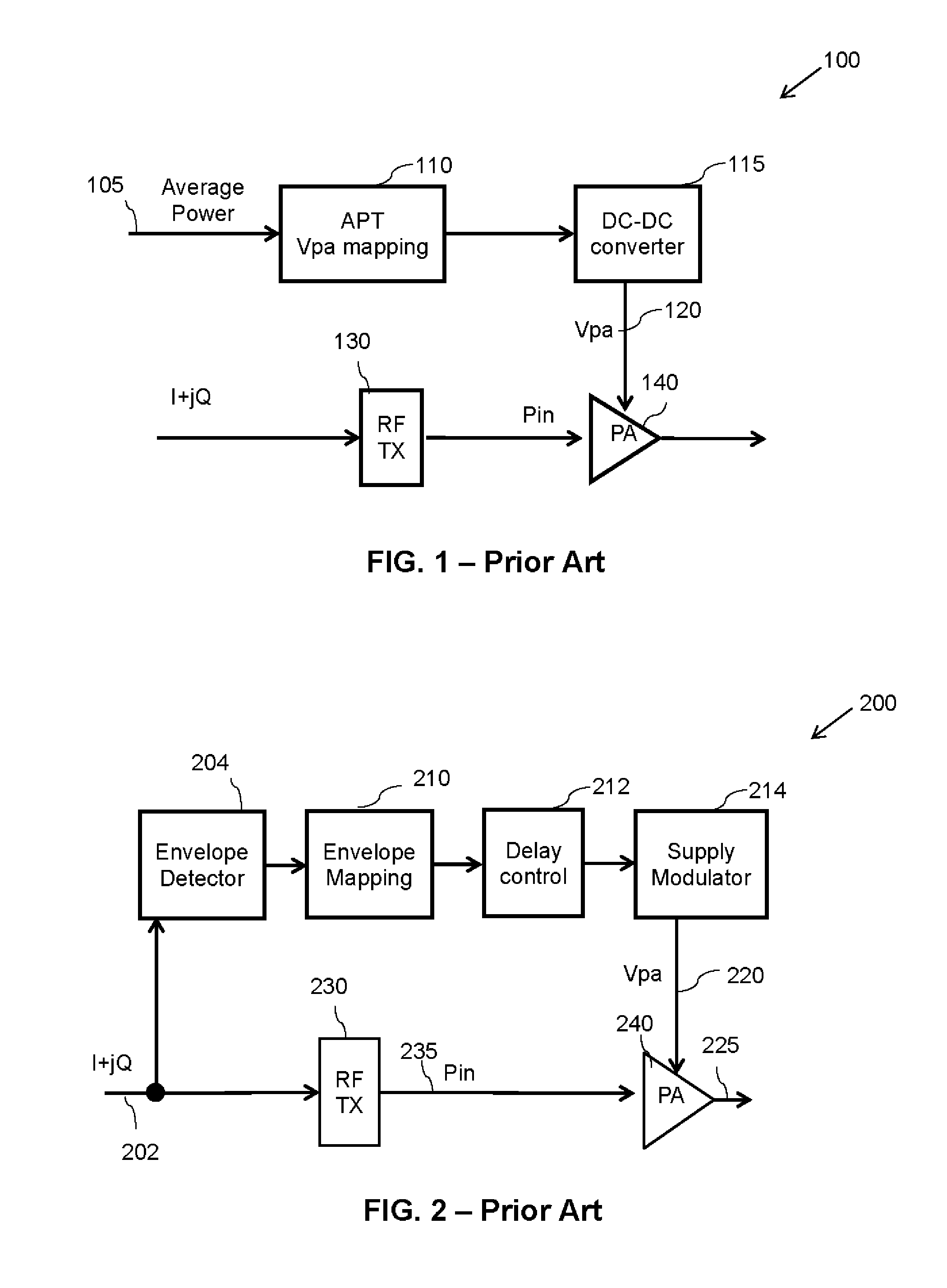
This technique is known to provide high efficiency, but the speed of signal tracking is limited.
One known problem with this technique is that APT operates with less efficiency at the higher output power levels when the peak to average power ratio (PAPR) back-off is large, which is predominantly the case for more complex modulation schemes.
However, the total system efficiency is affected by supply modulator efficiency that is related to the supply modulator design, supply voltage range, bandwidth and PA loading, which typically results in ET modulator efficiency not being high enough for most applications.
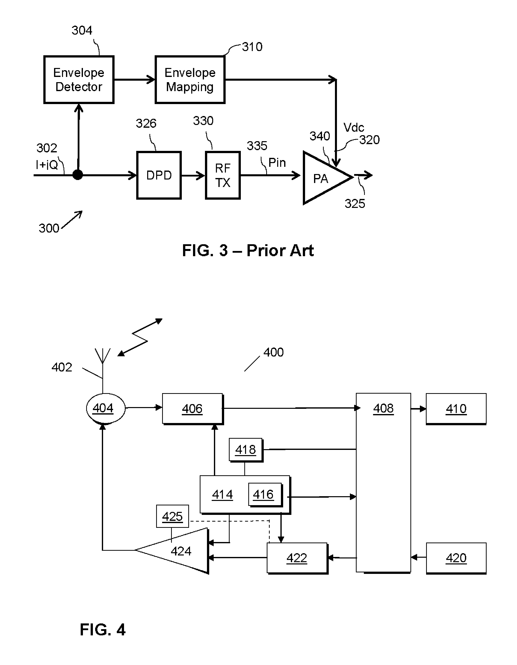
However, since the ET system is often a multichip implementation involving function blocks in digital baseband (BB), analogue BB, RF transceiver, power management and PA, consistent ET system performance cannot easily be guaranteed across all devices by hardware.
For example, a linear regulator / modulator design may be used, whereas although signal tracking is fast it is known to suffer from poor efficiency.
As a result of the poor efficiency, it is rarely, if ever, used for ET applications.
These requirements have an adverse impact on the hybrid modulator efficiency.
A paper titled ‘Slew-rate limited envelopes for driving envelope tracking amplifiers’ (by Gabriel Montoro, et al. and published by the Dept of Signal Theory and Communications by the Universitat Politecnica de Catalunya in Barcelona, Spain), describes a technique that sets a maximum value for a slew-rate limiter in an ET path, but has been identified as introducing some delays and out-of-band emissions of the supply modulator under varying load conditions.
A yet further paper titled ‘A DSP structure authorizing reduced-bandwidth DC / DC Converters for Dynamic Supply of RF Power Amplifiers in Wideband Applications’ (by Albert Cesari, et al. and published by the Groupe Integration de Systemes de Gestion de l′Energie in Toulouse, France), describes a technique that tracks a peak of an original envelope signal, but has been identified as also introducing some delays and creating poor out-of-band emissions of the supply modulator due to use of a DC / DC converter input step signal.

Method used


Image

  • Methods and apparatus for envelope tracking system
  • Methods and apparatus for envelope tracking system
  • Methods and apparatus for envelope tracking system

Examples


Embodiment Construction

[0050]Examples of the invention will be described in terms of one or more integrated circuits for use in a wireless communication unit, such as user equipment in third generation partnership project (3GPP™) parlance. However, it will be appreciated by a skilled artisan that the inventive concept herein described may be embodied in any type of integrated circuit, wireless communication unit or wireless transmitter that comprises or forms a part of an envelope tracking system. Furthermore, because the illustrated embodiments of the present invention may for the most part, be implemented using electronic components and circuits known to those skilled in the art, details will not be explained in any greater extent than that considered necessary as illustrated below, for the understanding and appreciation of the underlying concepts of the present invention and in order not to obfuscate or distract from the teachings of the present invention.

[0051]Examples of the invention will be describ...


PUM


Abstract

A communication unit includes a radio frequency, RF, transmitter having: a power amplifier, PA, module; and an envelope tracking system operably coupled to the PA module and having a supply modulator arranged to variably control a supply voltage for the PA module in response to a number of input samples of an envelope signal; wherein the envelope tracking system further includes at least one slew rate module arranged to re-distribute a maximum slew rate across the number of input samples in a provision of a variable power supply to the PA module.

Description

BACKGROUND[0001]1. Field of the invention[0002]The field of this invention relates to methods and apparatus for an envelope tracking system, and in particular to methods and apparatus for improving an efficiency of an envelope tracking system for a power amplifier module, for example within a radio frequency (RF) transmitter module of a wireless communication unit.[0003]2. Background of the Invention[0004]A primary focus and application of the present invention is the field of radio frequency (RF) power amplifiers capable of use in wireless telecommunication applications. Continuing pressure on the limited spectrum available for radio communication systems is forcing the development of spectrally-efficient linear modulation schemes. Since the envelopes of a number of these linear modulation schemes fluctuate, these result in the average power delivered to the antenna being significantly lower than the maximum power, leading to poor efficiency of the power amplifier. Specifically, in...

Claims


Application Information

Patent Timeline
Patent Type & Authority Applications(United States)
IPC IPC(8): H04B1/04
CPCH04B2001/0408H04B1/0475H04B2001/0416H03F3/24H03F2200/105H03F2200/465H03F2200/504H04L27/3411
Inventor YAN, SHENG-HONGHONG, HAO-PING
Owner MEDIATEK INC
Learn More