Nano-imprinting apparatus and method

a technology of nano-imprinting and apparatus, applied in the field of lithography, can solve the problems of inability to handle large area inability to achieve large-scale substrates in a single imprint step, and relatively time-consuming process, so as to alleviate, eliminate or mitigate one or more of the above-identified deficiencies in the art.

Inactive Publication Date: 2008-09-25
OBDUCAT AB SE
View PDF8 Cites 34 Cited by
  • Summary
  • Abstract
  • Description
  • Claims
  • Application Information

AI Technical Summary

Benefits of technology

[0006]With the above and the following description in mind, then, an aspect of the present invention is to provide a nano-imprinting apparatus and method, which seek to mitigate, alleviate or eliminate one or more of the above-identified deficiencies in the art and disadvantages singly or in any combination.

Problems solved by technology

Although this nano-imprinting process may be capable of mass production, it has hitherto been restricted to nano-imprinting on components with a small total area, typically only a few square centimeters.
This system is, however, not capable of handling large area substrates in a single imprint step.
Thus, this process is relatively time-consuming and, hence, also less optimum for large-scale production purposes.
Further, this imprint process suffers from the drawback that continuous structures which are larger than said template size cannot be produced.
All in all, this means that production costs may be too high to make this technique interesting for large-scale production of fine structure devices, especially on large area substrates or objects.

Method used


Image

  • Nano-imprinting apparatus and method
  • Nano-imprinting apparatus and method
  • Nano-imprinting apparatus and method

Examples


Embodiment Construction

[0058]Embodiments of the present invention will be described more fully hereinafter with reference to the accompanying drawings, in which embodiments of the invention are shown. This invention may, however, be embodied in many different forms and should not be construed as limited to the embodiments set forth herein. Rather, these embodiments are provided so that this disclosure will be thorough and complete, and will fully convey the scope of the invention to those skilled in the art. Like numbers refer to like elements throughout.

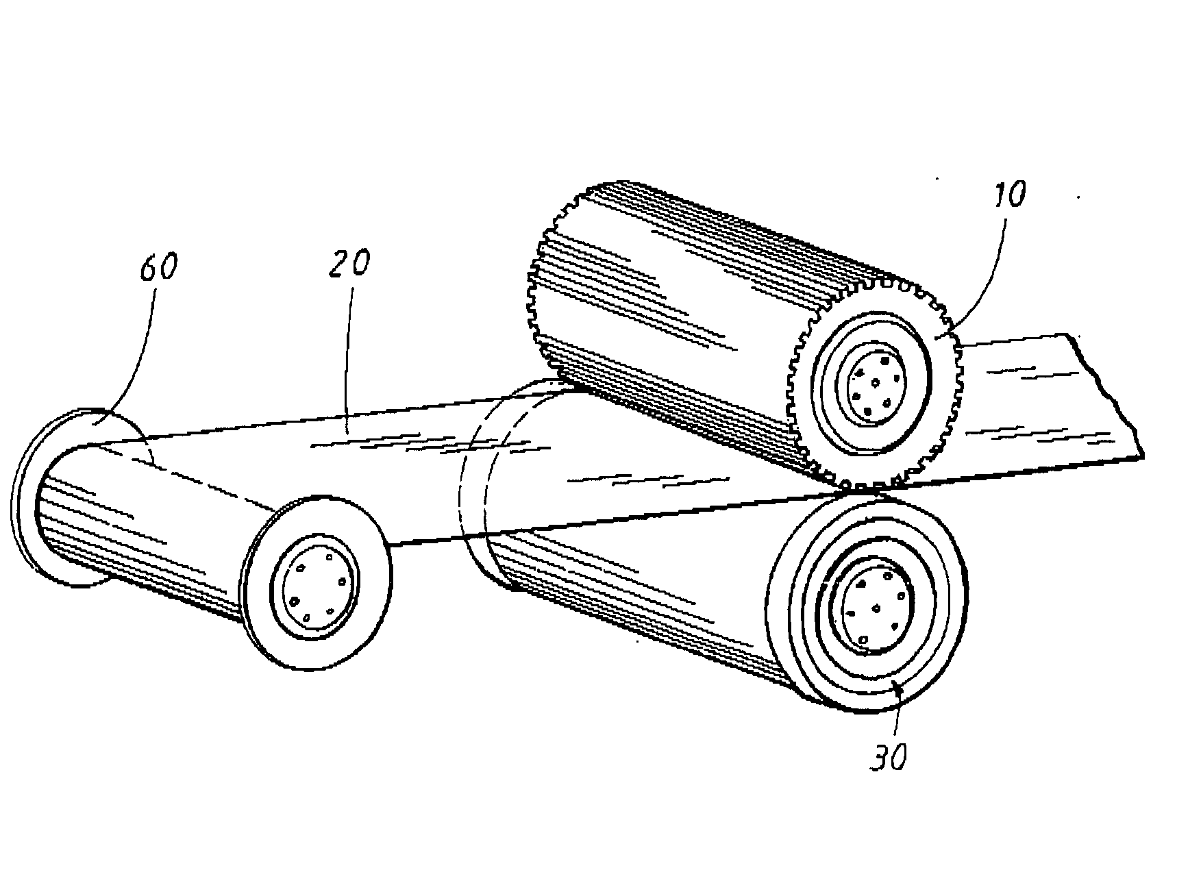
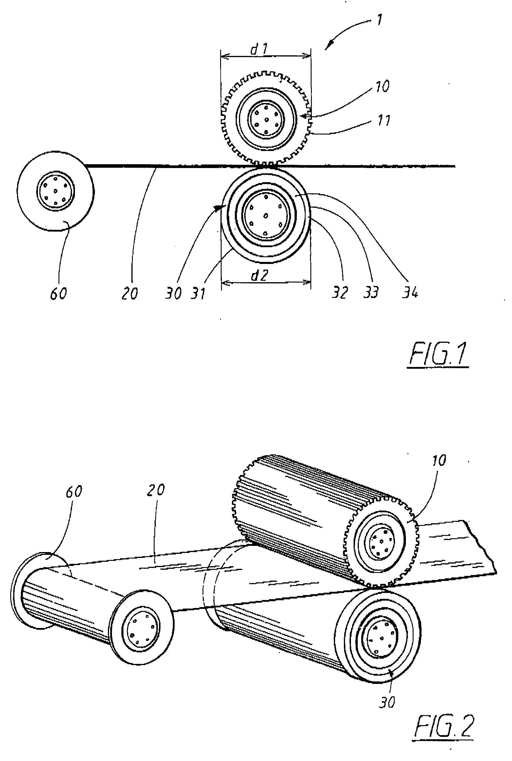
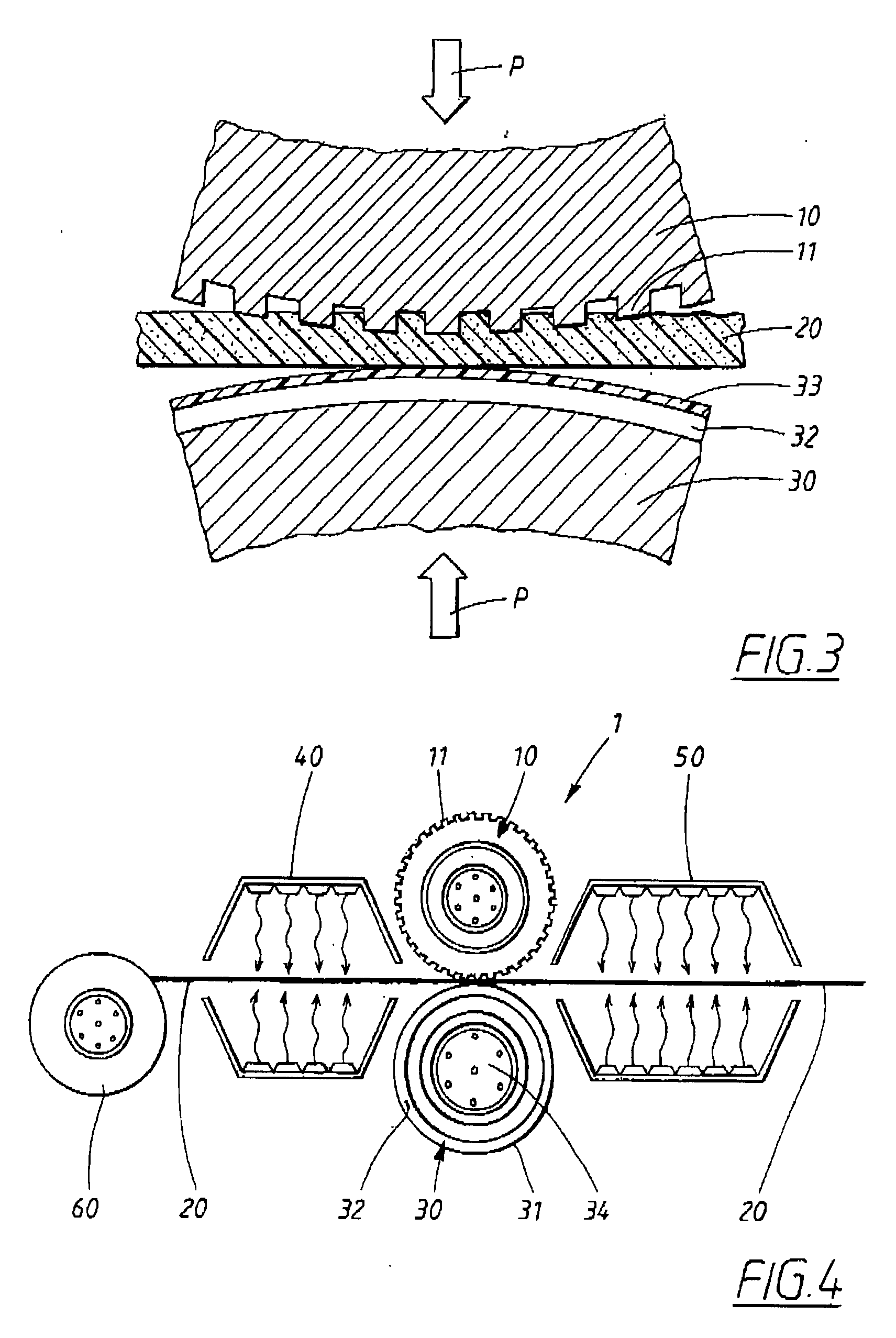
[0059]The present invention relates, in general, to a nano-imprinting apparatus and method for transferring a pattern from a template to a substrate. The present invention is based on a paradigm different from the prior art of nano-imprinting in that the template is in the form of a rotatably mounted roller to be brought into contact with the substrate to be patterned. Unlike current nano-imprinting apparatuses, some embodiments of the present invention a...


PUM

PropertyMeasurementUnit
pressureaaaaaaaaaa
thicknessaaaaaaaaaa
diameteraaaaaaaaaa

Abstract

An apparatus and a method in connection with the lithography of structures on a micro or nanometer scale. A nano-imprinting apparatus according to an embodiment of the invention comprises two rotatably mounted rollers for transferring a pattern of micro or nanometer size to the substrate to be patterned. A first rotatably mounted roller has a patterned circumferential surface for transferring a pattern from the first rotatably mounted roller to a deformable substrate by contacting the patterned surface with the substrate. A second rotatably mounted roller has a principally smooth circumferential surface which faces the patterned surface of the first rotatably mounted roller. Furthermore, the second rotatably mounted roller is rotatably coupled with the first rotatably mounted roller for synchronized rotation of the first and second rollers. The substrate is movable between the first and second rollers such that, when these rollers rotate with respect to each other, the patterned surface of the first rotatably mounted roller comes into contact with the substrate whereby this pattern is transferred from the patterned surface to the substrate.

Description

TECHNICAL FIELD OF THE INVENTION[0001]The present invention relates in general to lithography and, more particularly, to an apparatus and a method in connection with the lithography of structures on a micro or nanometer scale. In particular, the invention relates to nano-imprint lithography on large area substrates or objects.DESCRIPTION OF RELATED ART[0002]The trend in microelectronics is towards ever smaller dimensions. Commercial components are now manufactured with structures of less than one micrometer in size, but there is a need to go even further down in dimensions, to <100 nm. Research concerning nano-components has raised a demand for a commercially applicable manufacturing technique for components with dimensions of <10 nm.[0003]Some of the most interesting techniques for fabrication of micro and nanometer structures include different types of lithography. One of the most promising techniques for reproducing nanostructures—i.e. structures in the order of 100 nm or s...

Claims


Application Information

Patent Timeline
Patent Type & Authority Applications(United States)
IPC IPC(8): B31F1/20
CPCB29C59/04B29C2059/023G03F7/0002B82Y40/00B82Y10/00
Inventor HEIDARI, BABAK
Owner OBDUCAT AB SE
Why Eureka
Try Eureka