Eureka AIR delivers breakthrough ideas for toughest innovation challenges, trusted by R&D personnel around the world.

Oscillation circuit, oscillator, electronic apparatus, moving object, and frequency adjustment method of oscillator

a frequency adjustment method and oscillator technology, applied in oscillator generators, pulse automatic control, electrical equipment, etc., can solve the problems of difficult to change an output frequency, limitation of a variable range of an output frequency, and inability to perform electric correction such as changing setting data on the central frequency, etc., to achieve easy extension of a variable range of output frequency, high reliability, and high speed

Active Publication Date: 2015-07-02
SEIKO EPSON CORP
View PDF10 Cites 2 Cited by
  • Summary
  • Abstract
  • Description
  • Claims
  • Application Information

AI Technical Summary

Benefits of technology

This patent describes an oscillation circuit that can change its output frequency quickly and easily to adjust the central frequency. It also includes a variable capacitance circuit that allows for easy adjustment of the output frequency range. The circuit has low phase noise and is highly reliable, making it useful in electronic apparatus and moving objects. In addition, the circuit has a small amplitude and reduces energy requirements for transmission and reception, resulting in reduced noise levels. The power supply of the voltage controlled oscillation circuit is separated from the power supply of the oscillation portion of the PLL circuit, which prevents voltage fluctuations from affecting the power supply of the PLL circuit. Overall, this patent provides techniques to improve the performance and reliability of oscillation circuits.

Problems solved by technology

However, in the oscillator disclosed in JP-A-2012-64915, there are problems in that, in a case where a central frequency (an output frequency when a control voltage is a central voltage in a variable range) is changed, the quartz crystal vibrator is required to be changed, electrical correction such as changing setting data cannot be performed on the central frequency, and a limitation is put on a variable range of an output frequency.
In the oscillator disclosed in JP-T-2006-526946, since an operation speed of the ADC is limited, it is difficult to change an output frequency at a high speed (to increase an upper limit of a modulation bandwidth), and if the ADC is operated at a high speed, there is a concern that digital noise or power consumption may increase.

Method used


Image

  • Oscillation circuit, oscillator, electronic apparatus, moving object, and frequency adjustment method of oscillator
  • Oscillation circuit, oscillator, electronic apparatus, moving object, and frequency adjustment method of oscillator
  • Oscillation circuit, oscillator, electronic apparatus, moving object, and frequency adjustment method of oscillator

Examples


Embodiment Construction

[0049]Hereinafter, a preferred embodiment of the invention will be described with reference to the drawings. The embodiment described below does not improperly limit the content of the invention recited in the appended claims. Not all of the configurations described below are essential constituent requirements.

1. Oscillator

Configuration of Oscillator

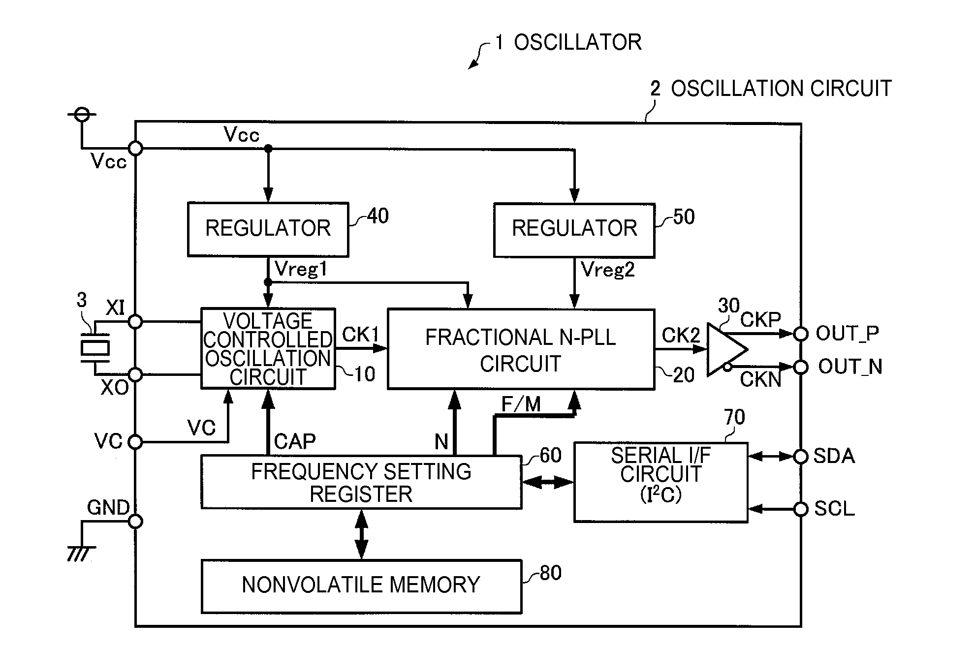
[0050]FIG. 1 is a configuration diagram of an oscillator of the present embodiment. As illustrated in FIG. 1, an oscillator 1 of the present embodiment includes an oscillation circuit 2 and a vibrator 3. The oscillation circuit 2 and the vibrator 3 are stored in a package (not illustrated).

[0051]In the present embodiment, the vibrator 3 is a quartz crystal vibrator in which quartz crystal is used as a substrate material, and, for example, an AT cut or SC cut quartz crystal resonator is used. The vibrator 3 may be a surface acoustic wave (SAW) resonator or a micro-electro-mechanical system (MEMS) vibrator. As a substrate material of the v...


PUM


Abstract

An oscillation circuit includes a voltage controlled oscillation circuit that includes a variable capacitance circuit provided with a variable capacitance element whose capacitance value is controlled on the basis of a control voltage and oscillates a vibrator so as to generate an oscillation signal, and a fractional N-PLL circuit that receives the oscillation signal generated by the voltage controlled oscillation circuit and includes a voltage controlled oscillator which controls an oscillation frequency on the basis of control input data (an integral division ratio and a fractional division ratio).

Description

BACKGROUND[0001]1. Technical Field[0002]The present invention relates to an oscillation circuit, an oscillator, an electronic apparatus, a moving object, and a frequency adjustment method of the oscillator.[0003]2. Related Art[0004]There is an ever increasing demand for an oscillator which can change a frequency output from an external terminal in a desired range in fields such as optical communications. As such an oscillator, there are known oscillators such as an analog type voltage controlled oscillator (for example, a voltage controlled crystal oscillator (VCXO)) in which a capacitance value of a load capacitor of an oscillation circuit changes depending on a control voltage which is applied to an external terminal and thus an output frequency changes, or a digital type oscillator in which a fractional N-PLL circuit is connected to a rear stage of a simple packaged crystal oscillator (SPXO), and an output frequency changes by changing a setting of the fractional N-PLL circuit fr...

Claims


Application Information

Patent Timeline
IPC IPC(8): H03L7/08H03B5/36H03L7/099
CPCH03L7/0802H03B5/366H03L7/099H03B5/326H03B2201/0208H03L7/1976H03L7/08
Inventor SAWADA, MITSUAKITORIUMI, YUICHI
Owner SEIKO EPSON CORP
Why Eureka
Eureka Blog
Learn More