Lithium battery auto-depassivation system and method

a lithium battery and auto-depassivation technology, applied in the direction of electric vehicles, charging/discharging, transportation and packaging, etc., can solve the problems of battery not meeting the peak pulse current requirements for certain functions, product unusability, and breakdown of protective layer

Active Publication Date: 2015-06-18
HONEYWELL INT INC
View PDF4 Cites 11 Cited by
  • Summary
  • Abstract
  • Description
  • Claims
  • Application Information

AI Technical Summary

Benefits of technology

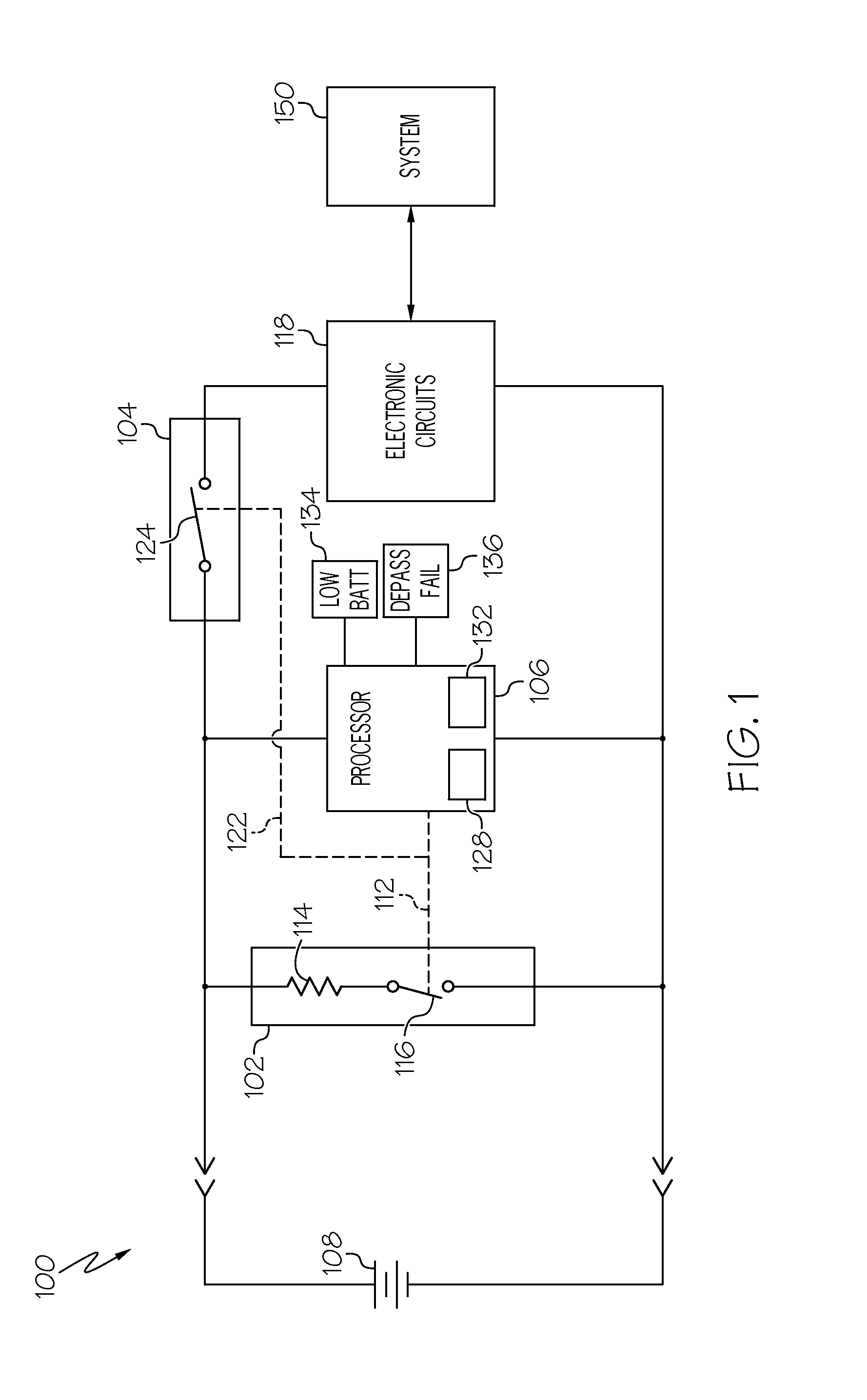
[0016]The depassivation circuit 102 may be variously configured and implemented. In the depicted embodiment, however, the depassivation circuit 102 includes a resistance 114 and a first controllable switch 116. The resistance 114 may be implemented using one or multiple resistors to exhibit a desired value of electrical resistance. In one particular embodiment, the resistance 114 is implemented using a single 18-ohm resistor. Though, again, this may vary. The first controllable switch 116 is responsive to the ENABLE signal 112 and may also be variously implemented. For example, it may be implemented using any one of numerous types of bipolar transistors or any one of numerous types of field-effect transistors. In one particular embodiment, the controllable switch 116 is implemented using a metal-oxide semiconductor field effect transistor (MOSFET).

Problems solved by technology

Although passivation is responsible for the relatively low self-discharge rate of lithium batteries, it also causes certain drawbacks.
This increased internal resistance may cause the battery to not respond to peak pulse current requirements for certain functions, such as wireless transmission.
This can, in some instances, render the product unusable.
It is generally known that applying a current drain to a lithium battery will breakdown the protective layer.
During a current drain, lithium ion movement is increased, which disturbs the ionic lattice of the protective layer, eventually breaking it down.
This process is called “depassivation.” The challenge in depassivation is to not load the battery, while effectively depassivating it.
Presently known methods thus rely on separate depassivation devices that require removal of the batteries from the end-use device and / or various other costly and / or labor intensive methods.

Method used


Image

  • Lithium battery auto-depassivation system and method
  • Lithium battery auto-depassivation system and method
  • Lithium battery auto-depassivation system and method

Examples


Embodiment Construction

[0014]The following detailed description is merely exemplary in nature and is not intended to limit the invention or the application and uses of the invention. As used herein, the word “exemplary” means “serving as an example, instance, or illustration.” Thus, any embodiment described herein as “exemplary” is not necessarily to be construed as preferred or advantageous over other embodiments. All of the embodiments described herein are exemplary embodiments provided to enable persons skilled in the art to make or use the invention and not to limit the scope of the invention which is defined by the claims. Furthermore, there is no intention to be bound by any expressed or implied theory presented in the preceding technical field, background, brief summary, or the following detailed description.

[0015]Referring to FIG. 1, a functional block diagram of a battery depassivation circuit 100 is depicted. The depicted circuit 100 includes a depassivation circuit 102, a battery connect / discon...


PUM


Abstract

A battery depassivation system includes a depassivation circuit, a battery connect/disconnect circuit, and a processor. The depassivation circuit is adapted to be electrically coupled in series with a battery. The depassivation circuit is also coupled to receive an ENABLE signal and is configured, upon receipt thereof, to draw current from the battery. The battery connect/disconnect circuit is adapted to be electrically coupled in series between the battery and one or more battery-powered electronic circuits. The battery connect/disconnect circuit is coupled to receive an ISOLATE signal and is configured, upon receipt thereof, to electrically disconnect the one or more battery-powered electronic circuits from the battery. The processor is adapted to couple to the battery and is configured, upon being coupled thereto, to determine if the battery needs depassivation and implement a depassivation routine if the battery is determined to need depassivation.

Description

TECHNICAL FIELD[0001]The present invention generally relates to depassivation of lithium batteries, and more particularly relates to a system and method for auto-depassivation of lithium batteries.BACKGROUND[0002]Many devices, including most hand-held wireless devices, use one or more batteries as the electric power source. One popular type of battery that is used is a lithium battery, such as a lithium thionyl chloride battery, due to its relatively high energy density and low self-discharge rate. The low self-discharge rate allows lithium batteries to exhibit a longer shelf life as compared to various other battery types.[0003]The main reason that lithium batteries have such a low self-discharge is that a protective layer is formed on these batteries during periods of non-use (e.g., storage). This protective layer begins forming during the manufacturing process, as soon as the electrolyte comes into contact with the lithium anode. The protective layer consists of lithium chloride ...

Claims


Application Information

Patent Timeline
Patent Type & Authority Applications(United States)
IPC IPC(8): H02J7/00
CPCH02J7/0075H02J7/0069
Inventor VENKATARAMANI, NANDAGOPALRAMAMURTHY, GAUTHAMHARI, SHINESREENIVASAN, MOHAN
Owner HONEYWELL INT INC
Why Eureka
Try Eureka