
Devices, systems and methods to determine area sensor

a technology of area sensors and devices, applied in the field of electronic systems, can solve the problems of inaccuracy in the determination of package loading and the limited scheme of bradley, and achieve the effect of improving the accuracy of weighing or counting items

Active Publication Date: 2015-06-18
JOHNSON & JOHNSON CONSUMER COPANIES
View PDF26 Cites 73 Cited by
  • Summary
  • Abstract
  • Description
  • Claims
  • Application Information

AI Technical Summary

Benefits of technology

The present invention allows for the accurate determination of the position of the load on a scale, which improves accuracy in weighing or counting items. Additionally, it allows for weighing objects or loads remotely from the scale.

Problems solved by technology

The above-referenced Bradley publication describes a counting scale that can count articles transferred relative to the scale, but the scheme of Bradley is limited to items that are relatively similar in weight.
Even if center-of-mass information could indicate package loading for specific packages, if the position of the package on the scale changes, the moved center of mass would introduce inaccuracies into the determination of package loading.

Method used


Image

  • Devices, systems and methods to determine area sensor
  • Devices, systems and methods to determine area sensor
  • Devices, systems and methods to determine area sensor

Examples


Embodiment Construction

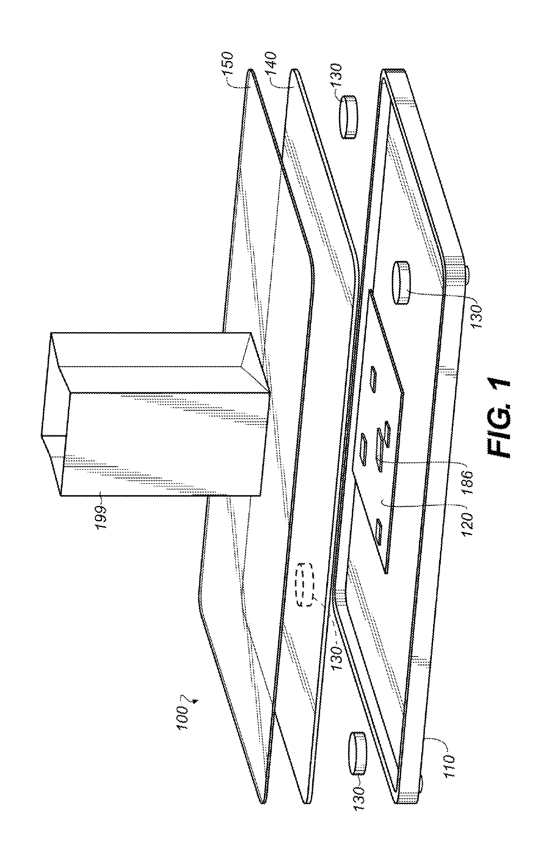
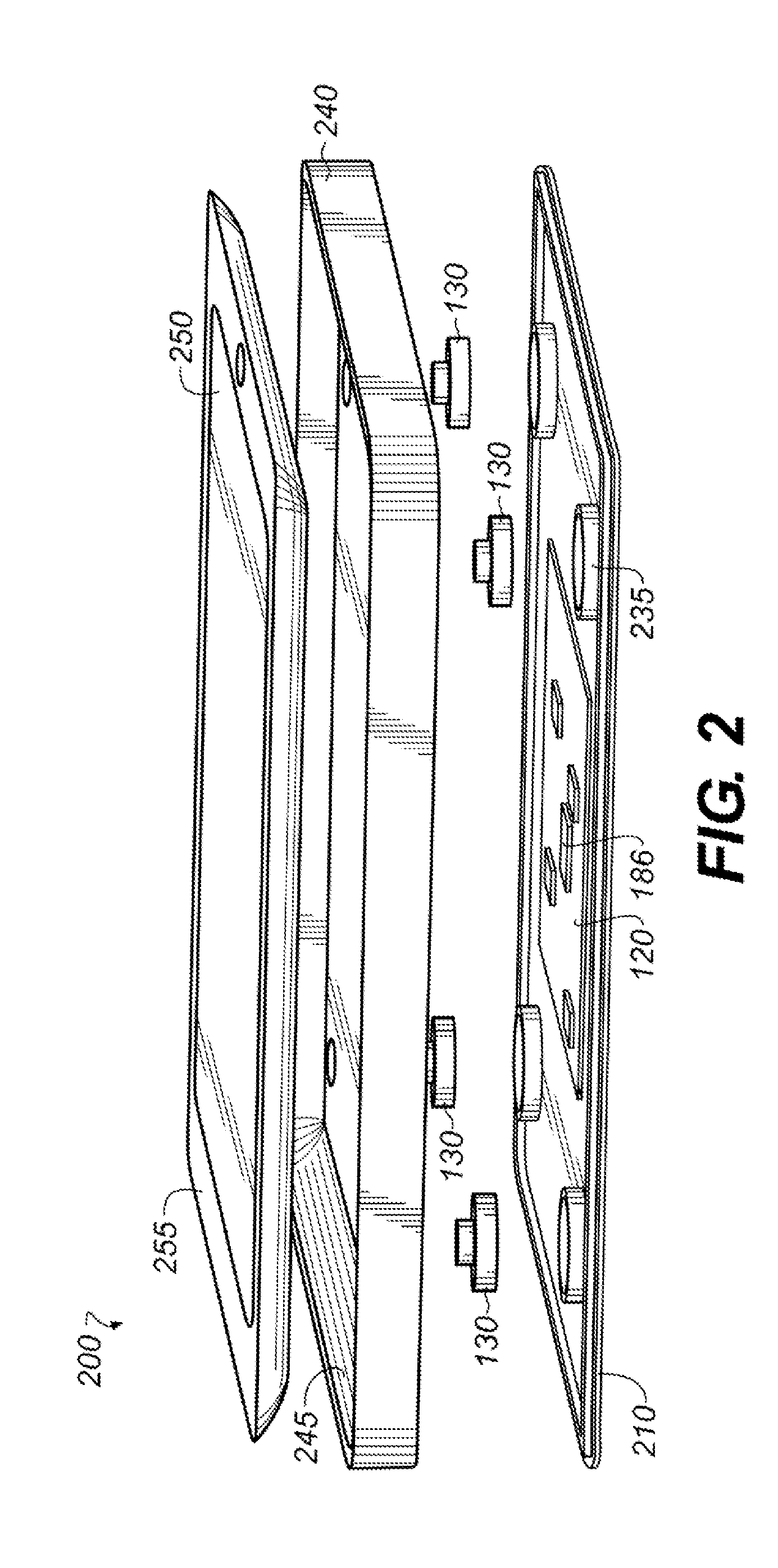
[0041]The following detailed description should be read with reference to the drawings, in which like elements in different drawings are identically numbered. The drawings, which are not necessarily to scale, depict selected embodiments and are not intended to limit the scope of the invention or the attached claims.

[0042]As used herein, the terms “about” or “approximately” for any numerical values or ranges indicate a suitable dimensional tolerance that allows the part or collection of components to function for its intended purpose as described herein. More specifically, “about” or “approximately” may refer to the range of values not at least ±10% of the recited value, e.g. “about 90%” may refer to the range of values from 81% to 99%. Also throughout the course of discussion, ranges or intervals are denoted using square brackets for closed endpoints and parentheses for open endpoints, as is conventional in the mathematical art. The terms “above” and “below” are not limiting as rega...


PUM


Abstract

A weighing scale includes a platform supporting a load. Force transducers beneath the platform output respective transducer force signals of the load. An area sensor above the platform outputs area force signals of load forces applied to respective spatial areas of the platform. A processor is configured to determine the load's weight and location on the platform based on the transducer force signals and the area force signals. A method of weighing the load is also described. A method of monitoring the load includes measuring first transducer force signal(s) and first area force signal(s) of the load, and then repeatedly measuring second force signal(s) of the load using the transducer(s) or area sensor until the first and second signal(s) indicate a change in a weight or location of the load. A changed weight or changed location of the load is then determined using the measured second force signal(s).

Description

TECHNICAL FIELD[0001]This application relates generally to the field of electronic systems for measuring weights of loads, e.g., objects or persons.BACKGROUND[0002]There are many different types of electronic weighing scales (herein, “scales”) in use today. One popular type of electronic weighing scale is constructed with a platform for receiving the load to be weighed and a set of levers, pivots, flexures, or torque tubes to mechanically combine the forces applied to the platform by the load, thereby enabling the measurement of these forces with a single electronic load cell, which operates as a force transducer. The load cell is typically constructed with a mechanically-deformable sensor plate with one or more sensor elements bonded thereto. When a load is applied to the load cell, the sensor plate mechanically bends and the sensor elements bonded thereto produce an electrical output signal, the magnitude of which is commensurate with the load applied to the load cell.[0003]Anothe...

Claims


Application Information

Patent Timeline
Patent Type & Authority Applications(United States)
IPC IPC(8): G01G3/12
CPCG01G3/12G01L1/26G01G19/414G01G19/52G01G21/28G01G23/00H04M1/0254H04M1/21H04M2250/12
Inventor LEE, CURTIS
Owner JOHNSON & JOHNSON CONSUMER COPANIES
Learn More