
Moulded body having specific cross-sectional structure

a cross-sectional structure and moulding technology, applied in the field of moulding bodies, can solve the problems of poor moldability, poor chemical resistance, and dependence of impact strength on thickness, and achieve the effects of suppressing or preventing the generation of sink marks, reducing the difference in resin amount, and reducing the difference in resin temperature drop ra

Active Publication Date: 2015-06-18
KANEKA CORP
View PDF2 Cites 1 Cited by
  • Summary
  • Abstract
  • Description
  • Claims
  • Application Information

AI Technical Summary

Benefits of technology

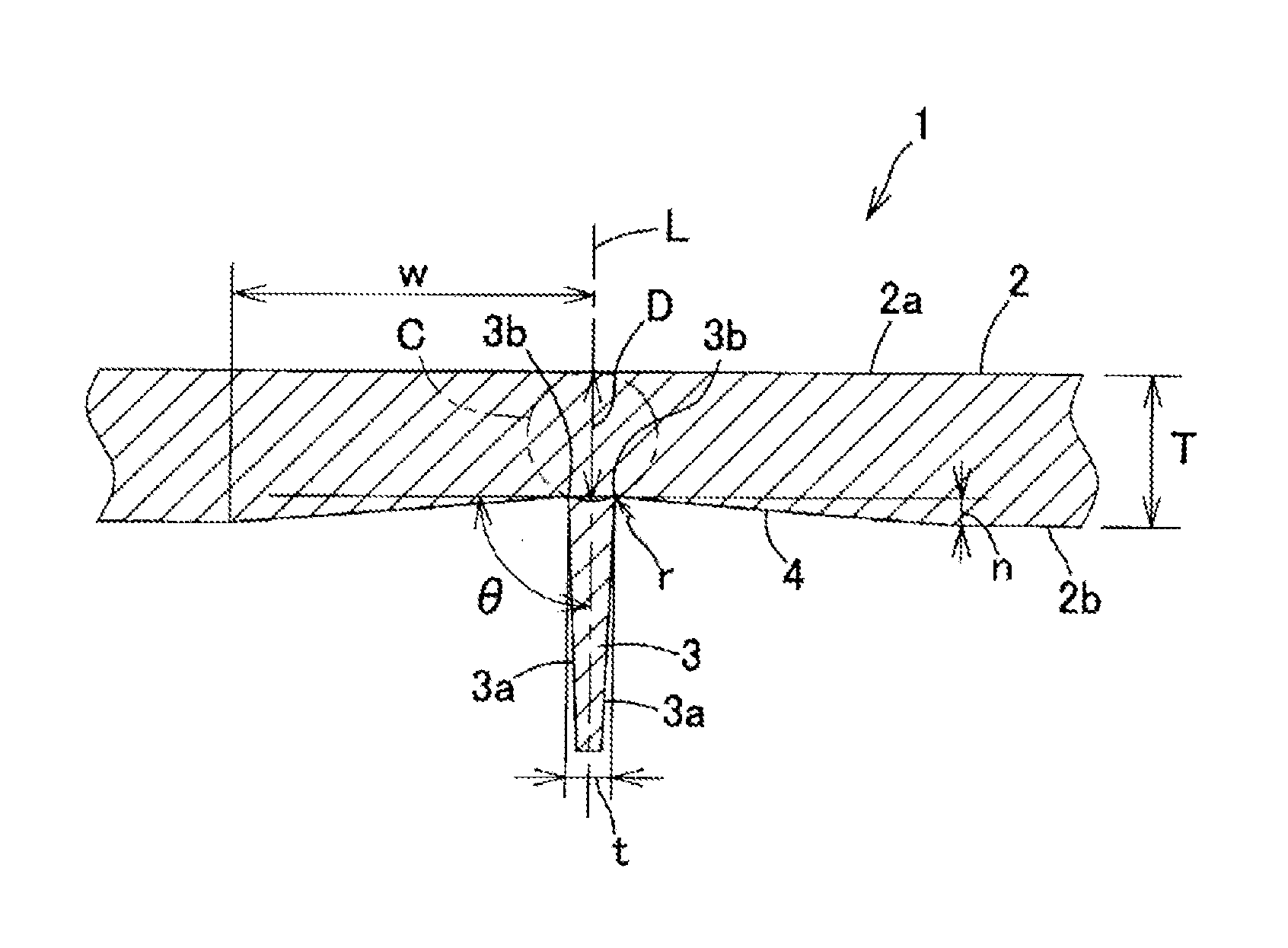
The present invention is a moulded body with a specific cross-sectional structure that reduces differences in resin between parts with and without ribs, and prevents the generation of sink marks and defects in the main body. The ratio D / T of 0.975 to 1.07 between the diameter of a circle and the thickness of the main body at an outer side of a reduced thickness part is provided to maintain sufficient strength and rigidity of the main body. The configuration of the moulded body also maintains a clear design surface without hollows, which enhances the overall appearance and quality of the moulded body.

Problems solved by technology

However, the polycarbonate resins have drawbacks such as poor chemical resistance, poor moldability, and dependence of impact strength on their thickness.
Thermoplastic polyesters have excellent chemical resistance and moldability but have drawbacks such as poor impact resistance and poor dimensional stability.
Such a resin composition has higher moldability but may have insufficient heat resistance for exterior parts of automobiles.
When the thickness of a moulded body is actually tried to be reduced, the resin composition of Patent Document 1, which is excellent as a molding material, is unfortunately, likely to become short shot during injection molding in some cases.
In order to solve the short shot, when the number of gates is increased, the number of welds are increased, and this may reduce the strength of a moulded body.
In order to solve the short shot, when the moulding temperature is set higher for improving the flowability, a resin composition is consequently, thermally degraded to generate a pyrolysis gas, leading to a poor appearance, in some cases.
When produced by using a resin composition similar to a conventional one and by using a mold designed with the same idea as the conventional one, the moulded body having a smaller thickness may have a lower rigidity as a whole, and such a new problem is required to be improved.
This method unfortunately has a problem.
In other words, a rib part having an excessively large thickness exerts high rigidity improvement effect but generates a hollow called a sink mark on the design surface of the outer surface of a molded product along the rib part, thus deteriorating the appearance.
In some cases by using such a method, the rib part cannot be filled with a resin composition, for example, and thus the method cannot achieve the balance between sufficient reinforcement effect and sink mark prevention.
Such a moulded body itself cannot be sufficiently filled with a resin composition in addition to the rib part, resulting in an unsatisfactory moulded body, in some cases.
Even when the moulded body is obtained, the rib part is insufficiently filled with a resin composition, failing to achieve the reinforcement effect, for example.
Conventional technology has a limitation to achieve a smaller thickness.

Method used


Image

  • Moulded body having specific cross-sectional structure
  • Moulded body having specific cross-sectional structure
  • Moulded body having specific cross-sectional structure

Examples


example 1

[0098]The resin composition of the present invention will next be specifically described with reference to examples.

[0099]In the following measurement conditions, examples, and the like, “part” and “%” mean “part by weight” and “% by weight”, respectively.

[0100]First, the materials used and measurement conditions will be described below.

[0101](Polycarbonate Resin)

[0102]The polycarbonate resin used was TARFLON A2200 (registered trademark) having a viscosity average molecular weight of 22,000 manufactured by Idemitsu Kosan Co., Ltd. It is represented as PC (A-1) in Table 2.

[0103](Polyester-Polyether Copolymers: B1 to B11)

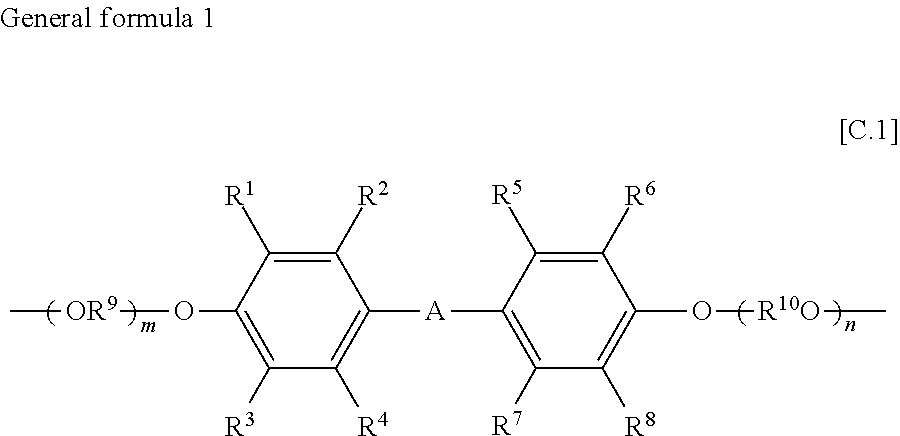
[0104]In a reaction vessel equipped with a stirrer and a gas outlet, polyethylene terephthalate (IV=0.65) prepared with a germanium catalyst, the modified polyether shown in Table 1, 400 ppm of germanium dioxide, and 2,000 ppm of a stabilizer (Irganox 1010 manufactured by Ciba Specialty Chemicals) on the basis of the total amount of the polyethylene terephthalate and ...

examples 1 to 8

, COMPARATIVE EXAMPLES 1 to 4

[0133]The resin composition of Production Example 5 was molded with an injection molding machine FE360S100ASE manufactured by Nissei Plastic industrial Co., Ltd. at a cylinder temperature of 280° C. and a mold temperature of 80° C., yielding an automobile panel part having a size of 600 mm×100 mm, or the large injection molded product having the rib structure shown in Table 4 and Table 5 as a test piece, and the moldability was evaluated. The part was coated with paint and then was visually observed whether sink marks were present or not. The evaluation standard was shown below. Table 4 and Table 5 also show the prediction results of sink marks calculated with CAE simulation, Mold-Flow.

[0134]Moldability

[0135]∘: Ribs are completely filled with a resin composition.

[0136]x: Ribs are not completely filled with a resin composition (short shot),

[0137]Evaluation of sink mark

[0138]∘: No sink mark is visually observed.

[0139]Δ: Sink marks are observed only when a ...


PUM

PropertyMeasurementUnit
thicknessaaaaaaaaaa
thicknessaaaaaaaaaa
thicknessaaaaaaaaaa

Abstract

A moulded body 1 includes a rib part 3 standing on a back surface 2b opposite to a design surface 2a of a main body 2 of the moulded body 1. A reduced thickness part 4 is formed on the back surface 2b of the main body 2, the ratio D / T is 0.975 to 1.07 where D is the diameter of a circle that passes through base ends 3b of both side faces 3a of the rib part 3 and is in contact with the design surface 2a of the main body 2 positioned between the base ends 3b, and T is the thickness of the main body 2 at an outer side of the reduced thickness part 4, and t<1.3(T−n) is satisfied where t is the thickness of the rib part 3, and n is the thickness of the reduced thickness part 4.

Description

TECHNICAL FIELD[0001]The present Invention relates to a moulded body having a specific cross-sectional structure preferably applicable to various parts in household appliances and vehicles.BACKGROUND ART[0002]Polycarbonate resins have been known to have the highest impact resistance of the engineering plastics and to have good heat resistance, and have been used in various fields by utilizing these characteristics. However, the polycarbonate resins have drawbacks such as poor chemical resistance, poor moldability, and dependence of impact strength on their thickness.[0003]Thermoplastic polyesters have excellent chemical resistance and moldability but have drawbacks such as poor impact resistance and poor dimensional stability.[0004]In order to take advantage of the characteristics of each material and to compensate for their drawbacks, various resin compositions including a combination of the polycarbonate resin and the thermoplastic polyester resin have been developed and studied t...

Claims


Application Information

Patent Timeline
Patent Type & Authority Applications(United States)
IPC IPC(8): B29C45/00B62D29/04
CPCB29C45/0025B62D29/04B29C2045/0043B29K2067/00B29L2031/3005B29K2105/0085B29K2069/00B29K2105/0088B29K2071/00C08L69/00C08L67/02C08L67/025C08K3/013Y10T428/24479C08L67/03
Inventor NAKATANI, KAZUSHIKAWAKUBO, HIDEKAZUSAEGUSA, KAZUNORI
Owner KANEKA CORP
Learn More