
Coordinated joint motion control system with position error correction

a motion control system and coordinate technology, applied in the field of computerized control systems, can solve the problems of compromising response time and precision in such simplified hydraulic control loops, affecting the efficiency of the hydraulic circuit, and affecting the accuracy of the control system, so as to achieve good absolute spatial positioning, good accuracy and repeatability, and the effect of reducing the number of errors

Inactive Publication Date: 2007-07-19
BOARD OF RGT NEVADA SYST OF HIGHER EDUCATION ON BEHALF OF THE UNIV OF NEVADA RENO
View PDF67 Cites 116 Cited by
  • Summary
  • Abstract
  • Description
  • Claims
  • Application Information

AI Technical Summary

Benefits of technology

[0012] c) applies a correction signal to the machine to reduce the difference.
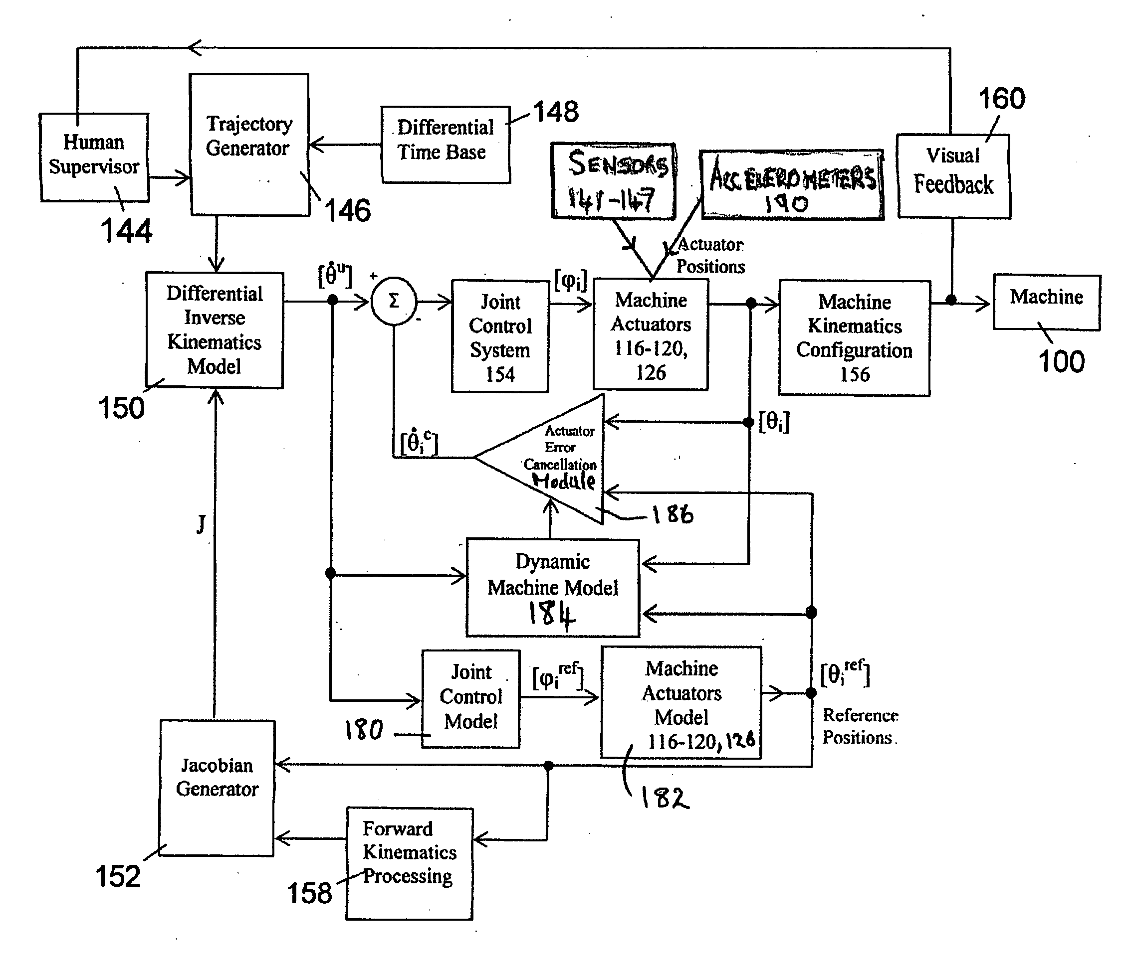
[0014] In one embodiment, the machine provides to the control system absolute position information regarding at least one movable machine element to facilitate determination of the end effector position. The machine can have multiple movable machine components contributing to movement of the end effector and the absolute position information can comprise absolute position information regarding each movable machine element. The position error correction system can comprise one or more of a joint control model, a machine actuators model and a dynamic machine model. If desired, the position error correction system can be effective to correct velocity error.
[0018] The invention also provides a control system for a machine as described, which control system comprises a position error correction module to correct discrepancies between the actual end effector trajectory and the desired end effector trajectory. The error correction module can compare the actual end effector position at a given point in time with a reference position appropriate for the desired end effector trajectory. Also, the error correction module can generate a difference signal indicating a difference between the actual end effector position and the reference position and can apply a correction signal to the machine to reduce the difference.
[0021] The control systems and methods of some embodiments of the invention enable the automated generation of useful working tool trajectories by articulated hydraulic machines and the like with considerable precision and repeatability. Such novel control systems can relieve an operator of a number of tedious, repetitive control functions permitting the operator to concentrate on overall machine positioning, trajectory selection and fine-tuning or trimming of tool action, and other concomitant functions.

Problems solved by technology

Implementation of kinematics transformation from a virtual model in the digital domain to a real world tool trajectory is a difficult task because of the reliance on imperfect mechanical sensors and actuators.
However, response time and precision may be compromised in such simplified hydraulic control loops.
In Danko '404 a drawback of this approach, is that the hydraulic circuit may not effectively and timely apply the desired control velocity to the machine elements or links, owing to hydraulic flow inertia or pressure deficiencies that may arise.
A drawback of such methods is that they may be computationally too extensive to be effectively used in embedded real-time control applications, where model computation time is significantly limited.
However, none of these proposals is entirely adequate to compensate for the mechanical inefficiencies that may arise in articulated hydraulic machinery under time- and task-variable, external loads.

Method used


Image

  • Coordinated joint motion control system with position error correction
  • Coordinated joint motion control system with position error correction
  • Coordinated joint motion control system with position error correction

Examples


example

Approximate Causal System Model

[0111] For an n-link machine, the joint angular positions x1, x2, . . . , xn can be denoted by the n-vector x=[x1, x2, . . . , xn]. A simplified motion equation can be written as a second-order vector differential equation [ref] between positions x, velocities dx / dt, and accelerations d2x / dt2: M⁡(x)⁢ⅆ2⁢xⅆt2+D⁡(x)⁢ⅆxⅆt+S⁡(x)⁢x=A⁡(ⅆxⅆt,x)(1)

[0112] In Eq (1), M(x), an n×n matrix that represents the moment of inertia and mass reduced to the joint axes. D(x), S(x) are n×n matrices of velocity-proportional drag and position-proportional spring torque coefficients, respectively. A(dx / dt, x) is an n-vector, representing an active torque vector, generated by the joint actuators. This term is a function of control signal u, velocity, and position vector variables.

[0113] Since all xi (i=1 . . . n) are functions of time t, the non-linear Eq (1) can be conveniently converted into a time-variant motion equation by eliminating x from the coefficient matrices: M⁡(...


PUM


Abstract

Disclosed are an articulated hydraulic machine supporting, control system and control method for same. The articulated hydraulic machine has an end effector for performing useful work. The control system is capable of controlling the end effector for automated movement along a preselected trajectory. The control system has a position error correction system to correct discrepancies between an actual end effector trajectory and a desired end effector trajectory. The correction system can employ one or more absolute position signals provided by one or more acceleration sensors supported by one or more movable machine elements. Good trajectory positioning and repeatability can be obtained. A two-joystick controller system is enabled, which can in some cases facilitate the operator's task and enhance their work quality and productivity.

Description

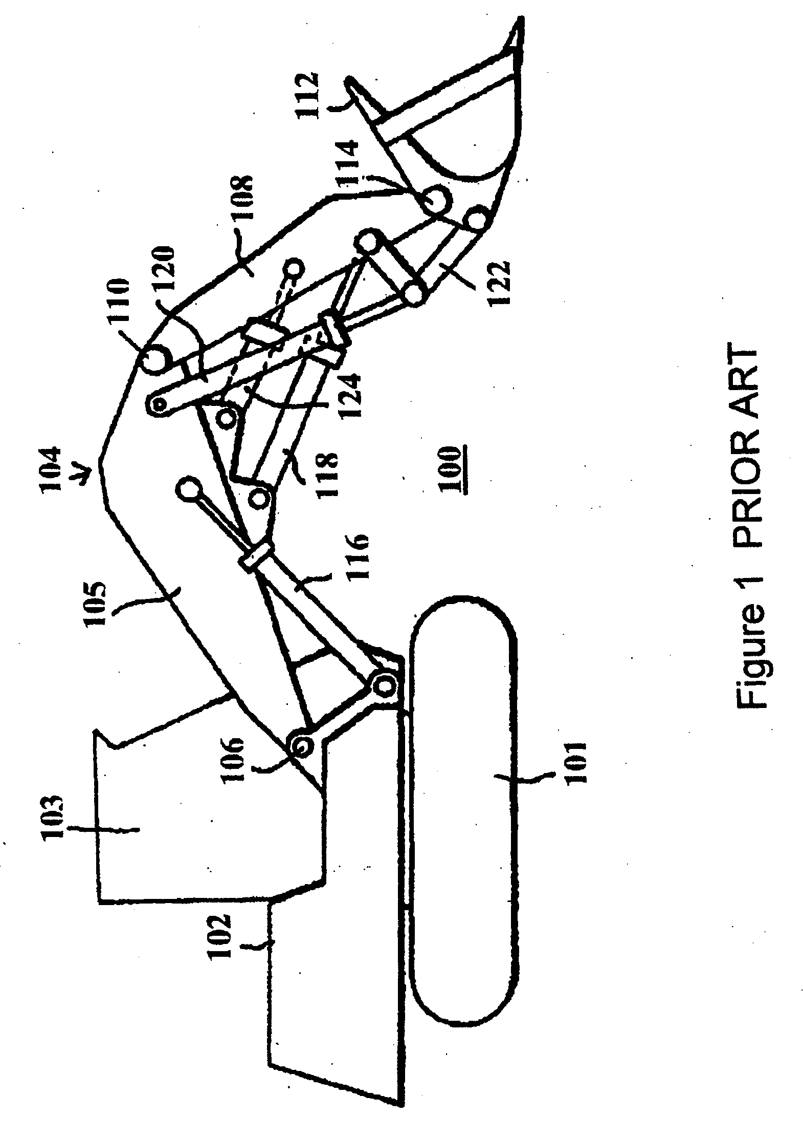
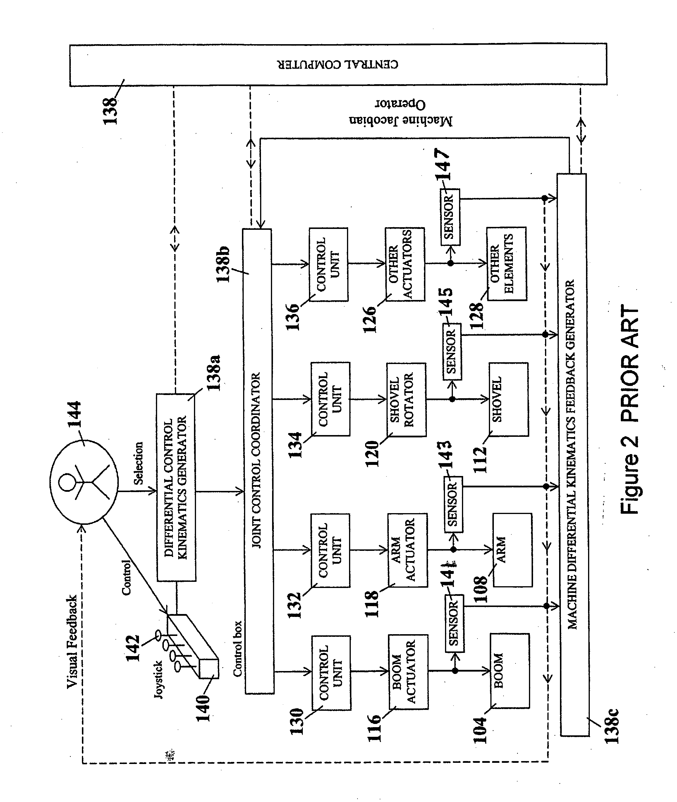
STATEMENT REGARDING FEDERALLY SPONSORED RESEARCH OR DEVELOPMENT (Not applicable.) FIELD OF THE INVENTION [0001] The present invention relates to a computerized control system for controlling hydraulic machinery of the type having an articulated arm carrying an end effector or tool at its extremity The invention is particularly, although not exclusively, applicable to control of coordinated joint systems, for example as employed in excavating equipment and certain three-dimensional image generators such as anatomic simulators. One non-limiting example of a machine that can benefit from the control systems and methods of the invention is a power shovel having an articulated arm supported from a rotatable turret and carrying a shovel or bucket at its extremity. BACKGROUND OF THE INVENTION [0002] Computer-assisted operator control of hydraulic machinery requires stable, smooth machine response. Danko U.S. patent application Ser. No. 10 / 488,011, Publication No. 20040267404, “referenced D...

Claims


Application Information

Patent Timeline
IPC IPC(8): G06F19/00
CPCB25J9/1628E02F9/2004E02F9/2029G05B13/021G05B2219/41273G05B2219/45012G05B2219/40495G05B13/041
Inventor DANKO, GEORGE
Owner BOARD OF RGT NEVADA SYST OF HIGHER EDUCATION ON BEHALF OF THE UNIV OF NEVADA RENO
Learn More