
Method for reducing the dendritic metal deposition on an electrode and lithium-ion rechargeable battery which uses this method

a technology of dendrite metal deposition and electrode, which is applied in the direction of secondary cell servicing/maintenance, sustainable manufacturing/processing, and final product manufacturing, etc., can solve the problems of significant prolongation of the cyclical and calendar service life of lithium batteries, suppress the formation of dendrites, and reduce dendrite metal deposition. , inhibit or suppress dendrite growth

Inactive Publication Date: 2015-05-28
ROBERT BOSCH GMBH
View PDF3 Cites 6 Cited by
  • Summary
  • Abstract
  • Description
  • Claims
  • Application Information

AI Technical Summary

Benefits of technology

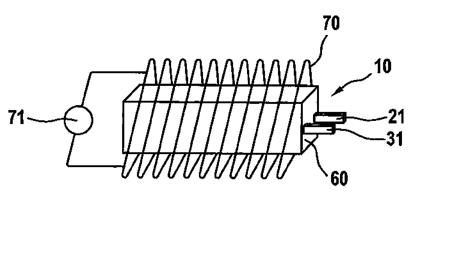
The present invention is about a method to prevent the growth of dendritic metal deposition on an electrode, particularly in rechargeable batteries. This method involves stabilizing a non-dendritic state of metal deposition at the electrode by generating a magnetic or electric field. This helps to generate a customized magnetic field that suppresses dendritic growth, especially in lithium-ion batteries. By inhibiting dendritic growth, this method prevents the formation of short circuits and prolongs the battery's life. Additionally, this method enables the use of larger, high-energy capacity batteries with lithium electrodes, which are lighter and have greater gravimetric energy density as compared to traditional batteries. In one embodiment, a solenoid is used to generate a magnetic field that stabilizes the non-dendritic state of metal deposition at the electrode. This method requires minimal current intensities and is powered by the rechargeable battery. Overall, this invention provides a way to prevent dendritic metal deposition and improve the performance of rechargeable batteries.

Problems solved by technology

By suppressing or inhibiting dendritic lithium metal growth, the electrolyte consumption of a lithium-ion rechargeable battery as a result of continuous SEI formation (SEI: solid electrolyte interface), i.e., a “running dry of the battery,” is prevented, which results in a significant prolongation of the cyclical and calendar service life of the lithium battery.

Method used


Image

  • Method for reducing the dendritic metal deposition on an electrode and lithium-ion rechargeable battery which uses this method
  • Method for reducing the dendritic metal deposition on an electrode and lithium-ion rechargeable battery which uses this method
  • Method for reducing the dendritic metal deposition on an electrode and lithium-ion rechargeable battery which uses this method

Examples


Embodiment Construction

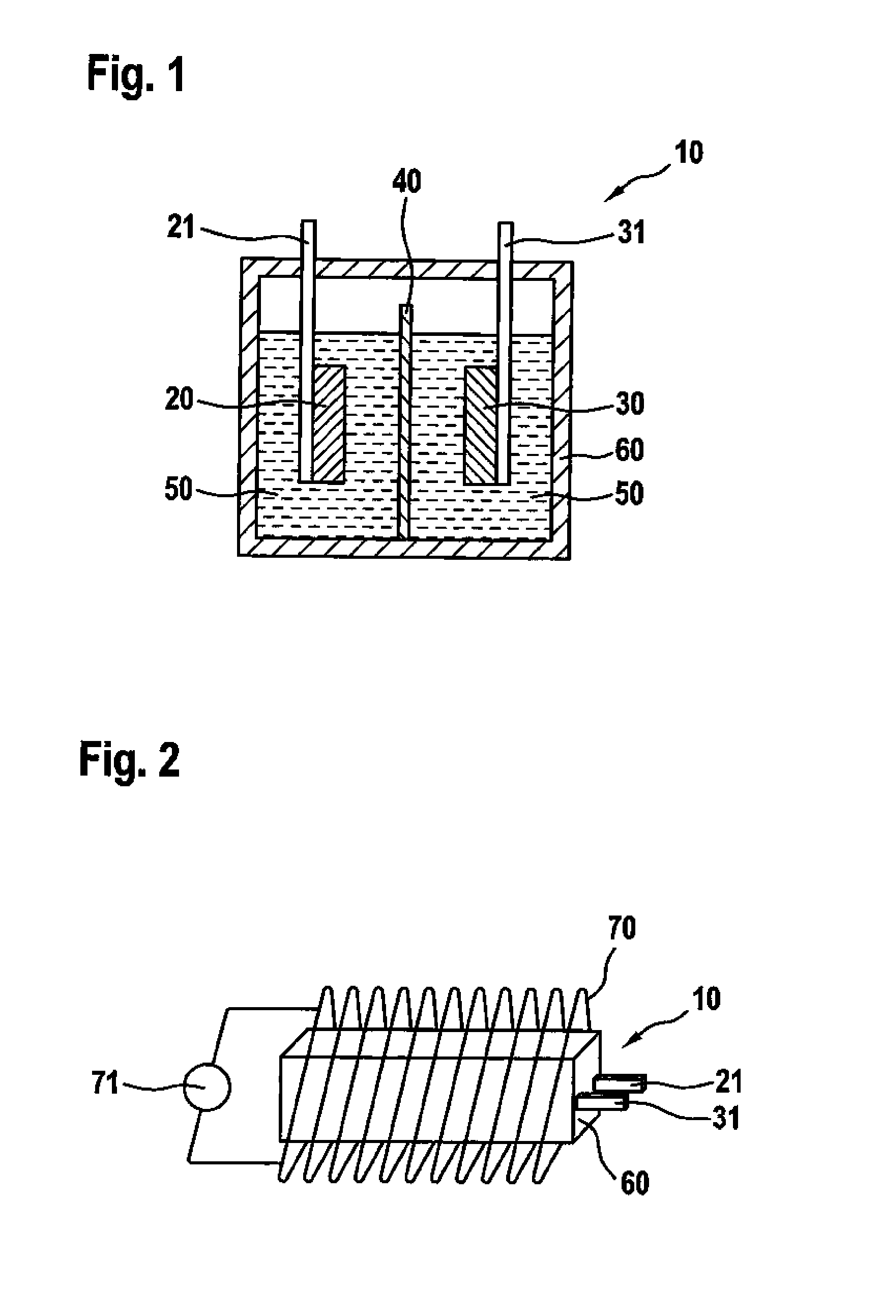
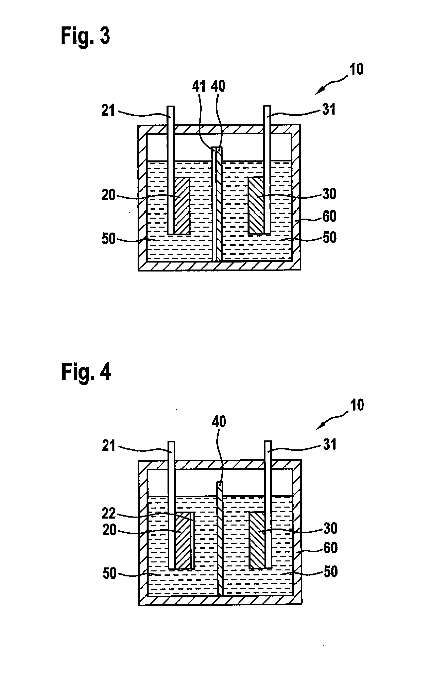
[0029]FIG. 1 shows a schematic cross sectional representation of a conventional lithium-ion rechargeable battery 10. An anode 20, which includes active anode material, is situated on an anode arrester 21. A cathode 30, which includes active cathode material, is situated on a cathode arrester 31. A separator 40 prevents interior short circuits from occurring between electrodes 20, 30, by isolating two electrodes 20, 30 spatially and electrically from one another. Situated between two electrodes 20, 30 is a liquid electrolyte 50. The latter typically includes a solvent and a lithium-containing salt. Two electrodes 20, 30, separator 40 and electrolyte 50 are situated together in a housing 60. Both anode arrester 21 and cathode arrester 31 penetrate housing 60, and thus enable the electrical contacting of anode 20 and cathode 30. If this lithium-ion rechargeable battery 10 is operated using non-classic electrode materials, for example, as a lithium-sulfur rechargeable battery or a lithi...


PUM


Abstract

In a method for reducing the dendritic metal deposition on an electrode, a non-dendritic state of the metal deposition is ascertained, and a magnetic or electric field is generated at the electrode and is modulated in such a way that it stabilizes the non-dendritic state of the metal deposition. The method is applied, e.g., to a lithium-ion rechargeable battery including an anode having an anode arrester, a cathode having a cathode arrester, and a separator, which are situated in a housing, in which a dendritic metal deposition at the anode is reduced with the aid of the method.

Description

BACKGROUND OF THE INVENTION[0001]1. Field of the Invention[0002]The present invention relates to a method for reducing the dendritic metal deposition on an electrode, and also relates to a lithium-ion rechargeable battery and a method for manufacturing a lithium-ion rechargeable battery.[0003]2. Description of the Related Art[0004]Novel lithium rechargeable battery concepts, for example, lithium-sulfur or lithium-air batteries, promise significantly higher energy densities as opposed to classic oxide lithium-ion rechargeable batteries. These new rechargeable battery concepts are the subject of intense research. One problem in this regard is the dendritic growth of the lithium anode during battery operation. This dendritic growth limits significantly the cyclical service life of the lithium-ion rechargeable battery and, in addition, represents a significant safety risk. Dendrites are able to perforate the separator and result in local short circuits. These local short circuits may in...

Claims


Application Information

Patent Timeline
IPC IPC(8): H01M10/42H01M10/48
CPCH01M10/48H01M10/4257H01M10/0525H01M2010/4271Y02E60/10Y02P70/50
Inventor BABA, NILUEFER
Owner ROBERT BOSCH GMBH
Learn More