
Modular handling system and method of using same

Active Publication Date: 2015-05-28
ROBOTICA INC
View PDF30 Cites 45 Cited by
  • Summary
  • Abstract
  • Description
  • Claims
  • Application Information

AI Technical Summary

Benefits of technology

The patent is for a collapsible wing that can be attached to a mobile base. The mobile base is a rectangular frame with four sides and the collapsible wings are four folding wings that can be connected to the sides of the mobile base. One of the collapsible wings can fold up to reduce floor space when not in use. The technical effect is a lightweight, versatile, and easy-to-use collapsible wing system that can be easily attached to a mobile base.

Problems solved by technology

Installing three phase power or central air system can be costly and may affect an acceptable return on investment (ROI).
There may be little or no space for permanently installed equipment.
In cases where cross dock operations may occur part of the time, permanently installed overhead equipment may be expensive and difficult to justify.
Large permanently installed systems may not justify the cost for part-time operations.
These options may provide desired functions, which may affect the functionality for make set-up and take-down.
Some versions may have more or less difficulty in assembly and / or may be more or less time consuming.
Additionally, selected versions may increase or decrease the foot print of the stored system.
Keeping up with the location of all stock can take weeks even months for stocker new to the position.
Stocking efficiency may slow until the store is learned.
In some cases, this configuration may not be suitable for sorting or case at rates beyond 30 CPM.

Method used


Image

  • Modular handling system and method of using same
  • Modular handling system and method of using same
  • Modular handling system and method of using same

Examples


example

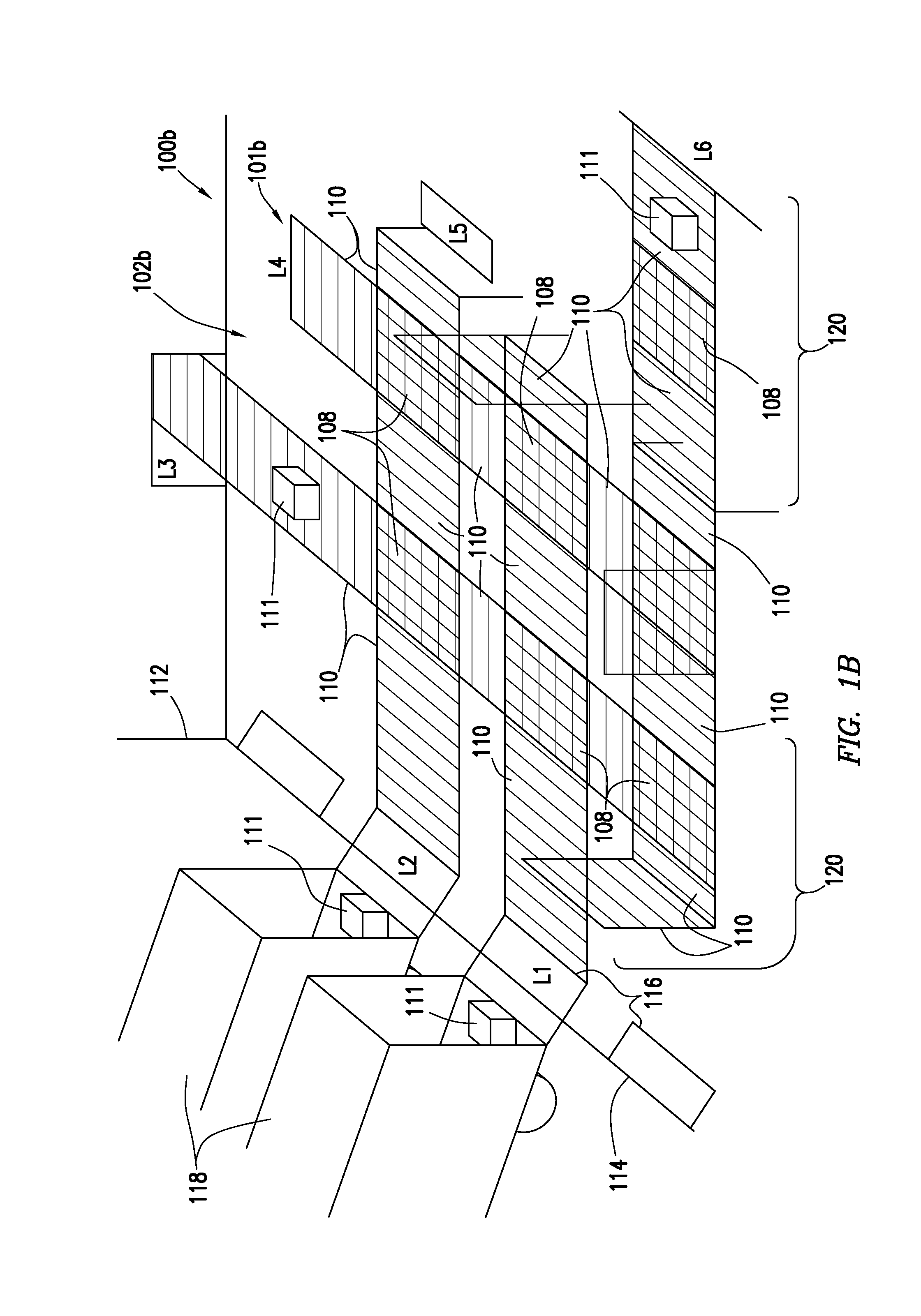
[0139]In the example of FIGS. 11A and 11B, as a case 111 enters the handling system 1101 at position F, it may be routed up to E, across to G, or down to J. The sorting system 744 F knows where each sorter 748 lies in the sorting system 744. F knows that any case 111 for A-E is passed up, any case 111 for G-I is passed across, and any case 111 for J-N is passed down. This may be accomplished by having each module 120 identify its neighboring module 120. A module 120 can determine when it is abutted by another. Modules, such as A, can identify that a module 120 exists to its right (B) and below it (E). Modules 120 with only one neighbor (D, I, N) may identify themselves as a terminal unit (i.e. the end of a line).

[0140]The module 120 then notifies its neighboring module 120 of what type of case 111 it is watching for (e.g., D1, D2, D3) which go to each of its three out-feed wings 110 at D1, D3. Module 120 at C, watches for cases 111 of types C1 and C2 which are routed to one of Unit ...


PUM


Abstract

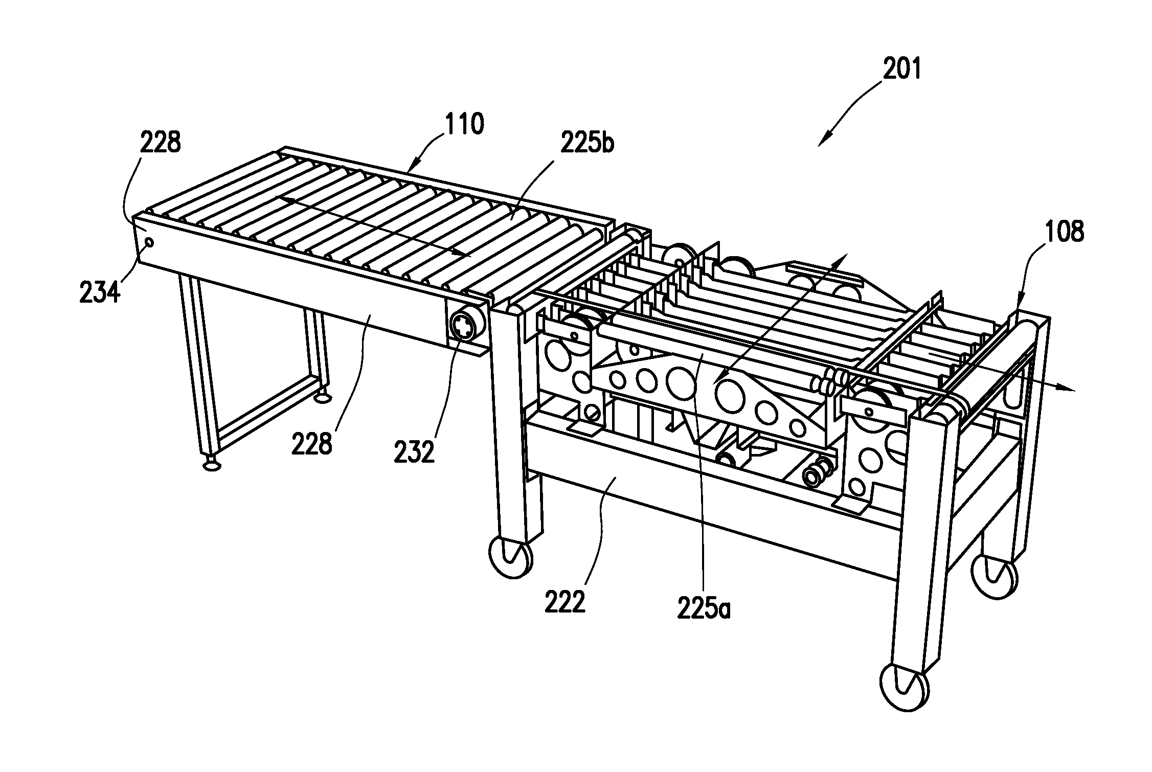
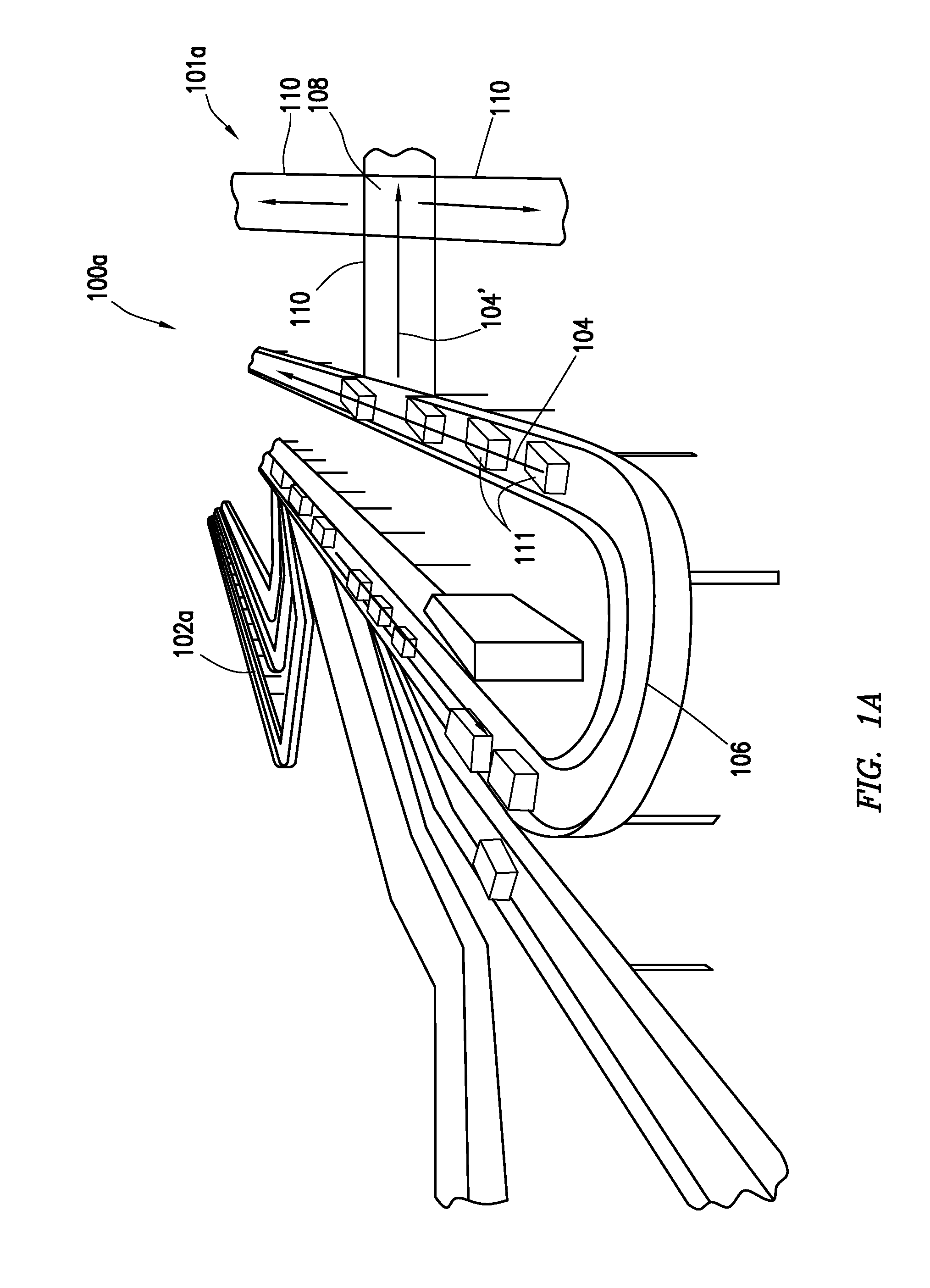
A modular handling system and method for transporting cases is disclosed. The system includes at least one mobile base including a base frame with a base diverter thereon and at least one collapsible wing. The base frame is supported by wheeled legs. The collapsible wing includes a wing frame. The wing frame is operatively connectable to the mobile base, and is supported by collapsible legs. The wing frame and the collapsible legs are movable between an operational position and a collapsed position whereby a configurable path is movably positionable about a work space. A sorting system including at least one sorter mounted to the mobile base(s) may also be provided. Each sorter is operatively connectable to the mobile bases to identify and route the cases. The sorters are interactively coupled for communication therebetween whereby the cases are selectively movable about the configurable path.

Description

[0001]This application claims priority to U.S. Provisional Application No. 61 / 907,418, filed on Nov. 22, 2013, the entire contents of which is hereby incorporated by reference herein. Applicant also has filed U.S. Patent Application No. 62 / 053,009, the entire contents of which is hereby incorporated by reference herein.BACKGROUND[0002]This present disclosure relates generally to handling equipment. More specifically, the present disclosure relates to conveyors, sorters, and / or related equipment used in handling materials.[0003]Conveyors include mechanical structures extending from one location to another to move the materials between such locations. For example, manufacturing industries may use conveyors to pass product components between workstations at the locations to enable assembly of the product components into a finished product. Such conveyors are fixed in place (e.g., bolted to the floor) in a manufacturing facility, and include frames with rollers or belts that enable the ...

Claims


Application Information

Patent Timeline
IPC IPC(8): B07C5/36B65G13/02B65G13/08B65G13/12
CPCB07C5/36B65G13/08B65G13/02B65G13/12B65G21/14B65G41/002B65G41/008B65G2207/30
Inventor DUGAT, JAY MARK
Owner ROBOTICA INC
Learn More