
Combined frictional false twisting device for ring spinning frame

a false twisting and friction technology, applied in the field of textile industry, can solve the problems of increasing the risk of slipping, and affecting the quality of the finished product, so as to reduce the twisting triangle height, reduce the twisting triangular area, and improve the yarn strength

Inactive Publication Date: 2015-05-14
INST OF WOOL & HEMP TEXTILE SCI SHANGHAI
View PDF12 Cites 3 Cited by
  • Summary
  • Abstract
  • Description
  • Claims
  • Application Information

AI Technical Summary

Benefits of technology

The invention is a modular friction false twist device that improves yarn twist distribution, spinning strength, and reduces spinning tension in ring spinning machines. It increases the yarn twist between the front roller nip and the false-twister, resulting in a reduction of the twisting triangle height. This results in increased yarn strength, improved yarn evenness, and reduced spinning tension in the twisting triangular area. Additionally, it reduces yarn breakage and improves yarn durability.

Problems solved by technology

Traditional ring spinning machine has a unique twist mechanism, and the special structure of yarn spinning, resulting in soft and fluffy yarn, cannot be replaced by any new spinning technology.
However, with the development of the modern textile industry, people pays more attention to the inherent defects of the ring spinning machine.
The prolonged production practice shows that the key technical bottlenecks of the ring spinning machine are spinning end breakage and unevenness, the strength of the yarn which in twisting triangle area is less than the spinning tension leads to the spinning end breakage and unevenness.
The adverse consequences of excessive spinning tension acting on the twisting point are that the fibers in the yarn will slip to produce unexpected draft, making the yarn uneven and increasing snicks.
Even the spinning end may break.
Increasing the yarn twist can increase the holding force of fibers, but increasing the twist of the twisting triangle can only reduce the twisting triangle height, and increasing the fibers can be held by the roller.
Because of the above defects of the ring spinning machine, application of the ring spinning machine is limited.
The disadvantages are that the spinning strength did not increase but decrease, and the friction between the yarn and bobbin becomes severe causing more lint;(2) Using the magnetic rotary yarn guide in place of the yarn guide.
The disadvantages are that the splicing operation is inconvenient, the high manufacturing cost of the yarn guide, and the low efficiency of false-twist.(3) Chinese patent No. 201010237244.3 discloses a high-strength, low-tension spinning device, equipped with yarn tension damping needle holding the false twist.
The disadvantage is that the splicing operation being inconvenient;(4) Chinese patent No. 201110129873.9 discloses using a pair of the dust cage in the form of friction false twist to compact wet spinning.
The disadvantage is that the suction of the dust cage motor needs more power;(5) Chinese patent No. 02118588.3 proposes a method and apparatus to reduce spinning tension, spun low twist yarn.
The disadvantage is that the spinning strength cannot be improved.
Except for more convenient operation, it has the same defects and problems.

Method used


Image

  • Combined frictional false twisting device for ring spinning frame
  • Combined frictional false twisting device for ring spinning frame
  • Combined frictional false twisting device for ring spinning frame

Examples


Embodiment Construction

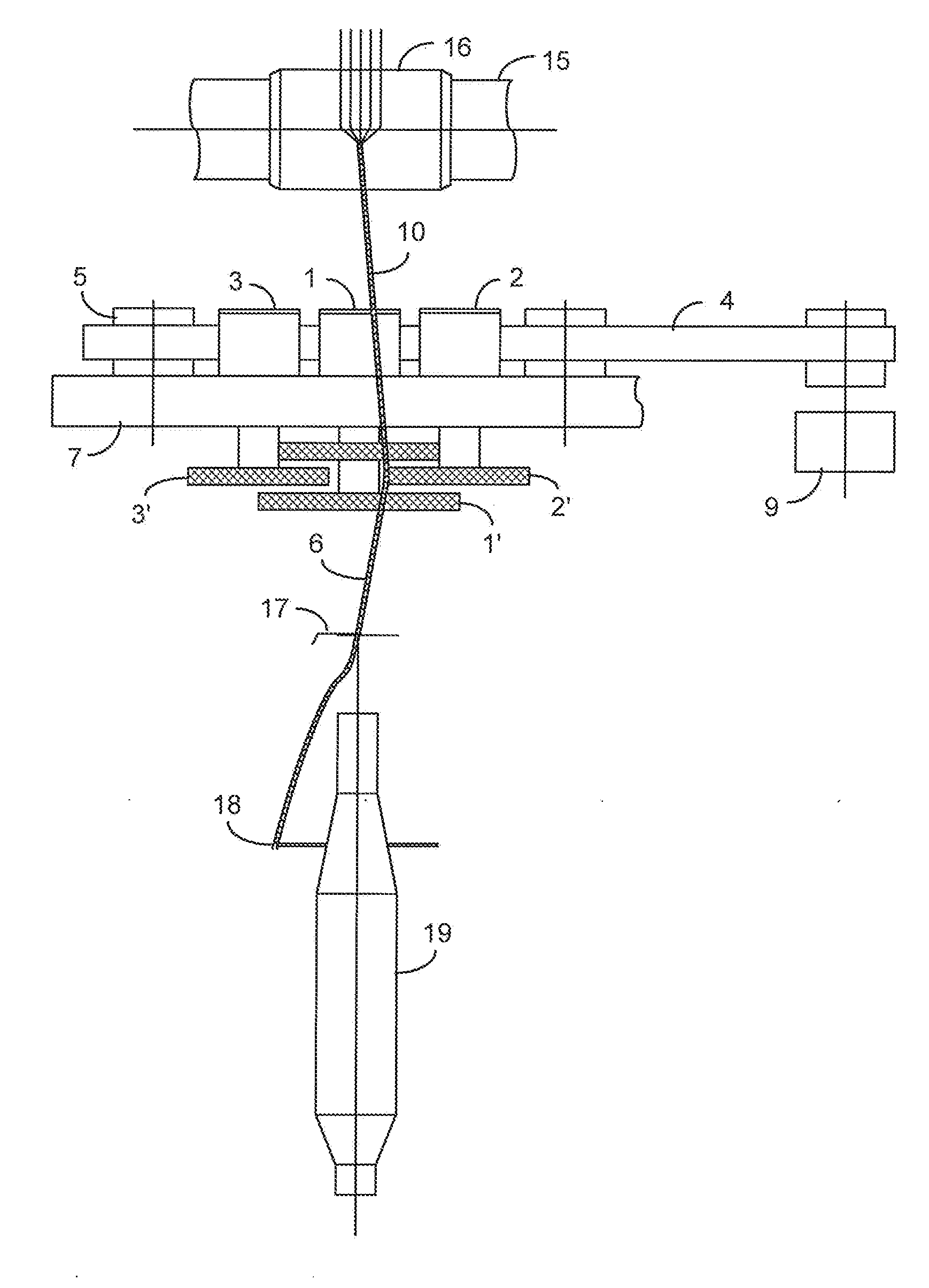
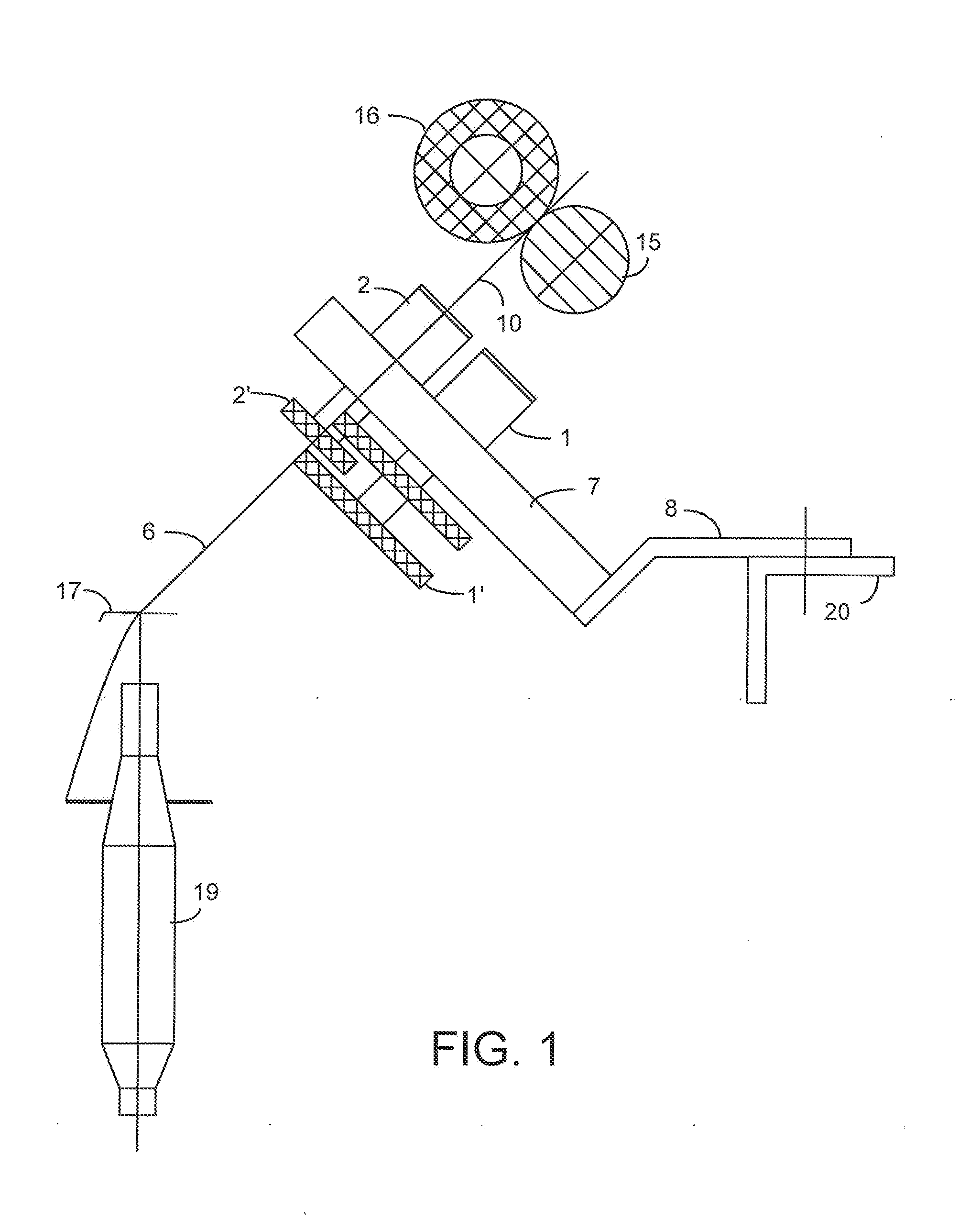
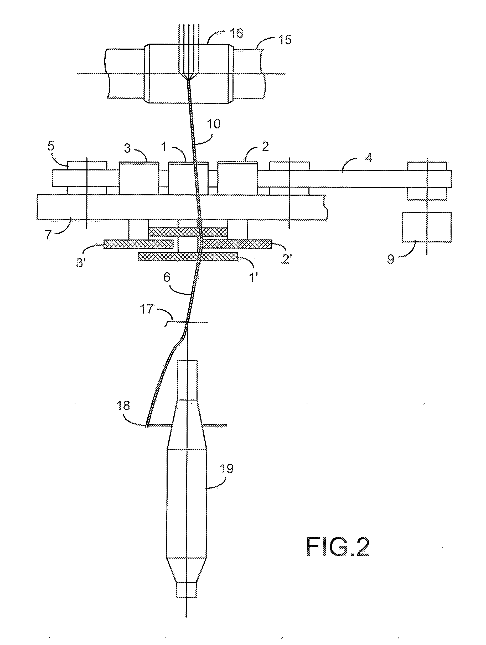
[0031]As the yarn is outputted from the front nip of the front roller 15 and the front rubber roller 16 to the false twisting device, it is placed among the outer peripheral surfaces of the friction plates. The yarn is put through a yarn guide 17, and finally wound on a yarn pipe 19. When spinning Z-twist yarns, the yarn is rubbed by the middle mandrel friction plate 1′ and right mandrel friction plate 2′. The friction plates 1′ and 2′ are rotated in the same clockwise direction, while the yarn rotates in the counter-clockwise rotation. When spinning S-twist yarns, the yarn is rubbed by the middle mandrel friction 1′ and left mandrel friction plate 3′. The friction plates 1′ and 3′ are rotated in the same counterclockwise direction, while the yarn rotates in the clockwise rotation.

[0032]Through the action of the frictional false twister, the twist of the yarn between the false-twist device to the front nip can be increased, shortening the twisting triangle height, and increasing the...


PUM

PropertyMeasurementUnit
plurality of frictionaaaaaaaaaa
diameteraaaaaaaaaa
strengthaaaaaaaaaa

Abstract

A frictional false twister is disclosed. The twister has a plurality of rotating friction plates located between the nip of the front rollers and the yarn guide. The friction plates are staggeringly arranged for rubbing a twisted yarn. The spinning direction of the twisted yarn is opposite to the rotating direction of the friction plates. Through the action of the frictional false twister, the twist of the yarn between the false twisting device to the front nip can be increased, shortening the twisting triangle height, and increasing the spinning strength. As the yarn and the outer surface of the friction plate make relative sliding and rubbing, the friction damping force correspondingly reduces the spinning tension in the twisting triangle.

Description

TECHNICAL FIELD[0001]The present invention relates to the field of textile industry, specifically refers to a friction false twisting device for use in a ring spinning machine.BACKGROUND OF INVENTION[0002]Since 1830, the traditional ring spinning machine was invented, more than 180 years has passed and has become the world's largest, the most widely used spinning main equipment. Spinning production capacity of China's textile industry has been more than 50% of the global total, there are 120 million cotton spindles and about 4 million wool spindles.[0003]Traditional ring spinning machine has a unique twist mechanism, and the special structure of yarn spinning, resulting in soft and fluffy yarn, cannot be replaced by any new spinning technology.[0004]However, with the development of the modern textile industry, people pays more attention to the inherent defects of the ring spinning machine. The prolonged production practice shows that the key technical bottlenecks of the ring spinnin...

Claims


Application Information

Patent Timeline
Patent Type & Authority Applications(United States)
IPC IPC(8): D02G1/08D01H7/92
CPCD01H7/923D02G1/087D02G1/06D02G1/082
Inventor FANG, LEIZHANG, DELIANGWANG, LINYAOHE, XIHUIZHOU, WENHUASONG, YUNLIAO, SHIMINDAI, ZIYLLAN, HONGYANHUA, GENDAWAN, XIAOYAN
Owner INST OF WOOL & HEMP TEXTILE SCI SHANGHAI
Learn More