Robot, robot system, and robot control apparatus

a robot and control apparatus technology, applied in the field of robots, can solve problems such as lack of versatility of image processing apparatuses and rust in work environments

Active Publication Date: 2015-05-07
SEIKO EPSON CORP
View PDF11 Cites 9 Cited by
  • Summary
  • Abstract
  • Description
  • Claims
  • Application Information

AI Technical Summary

Benefits of technology

The patent application uses a robot's housing as a background for image pickup, which allows for accurate and quick image processing without complicated algorithms. This results in versatile and stable inspection.

Problems solved by technology

Therefore, stain and rust in a work environment occur.
Therefore, the image processing apparatus lacks versatility.

Method used


Image

  • Robot, robot system, and robot control apparatus
  • Robot, robot system, and robot control apparatus
  • Robot, robot system, and robot control apparatus

Examples


Embodiment Construction

[0044]An embodiment of the invention is explained below with reference to the drawings.

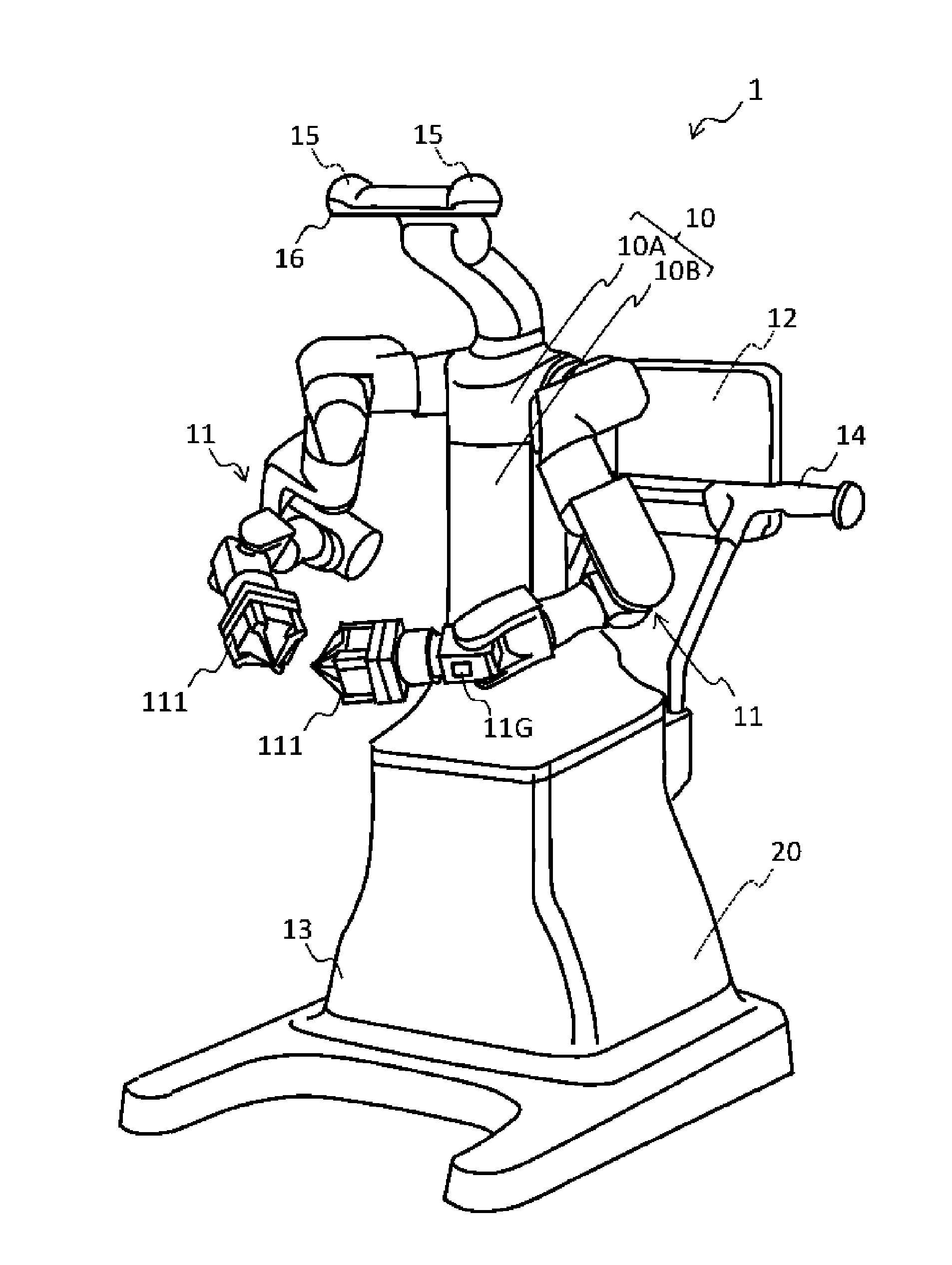
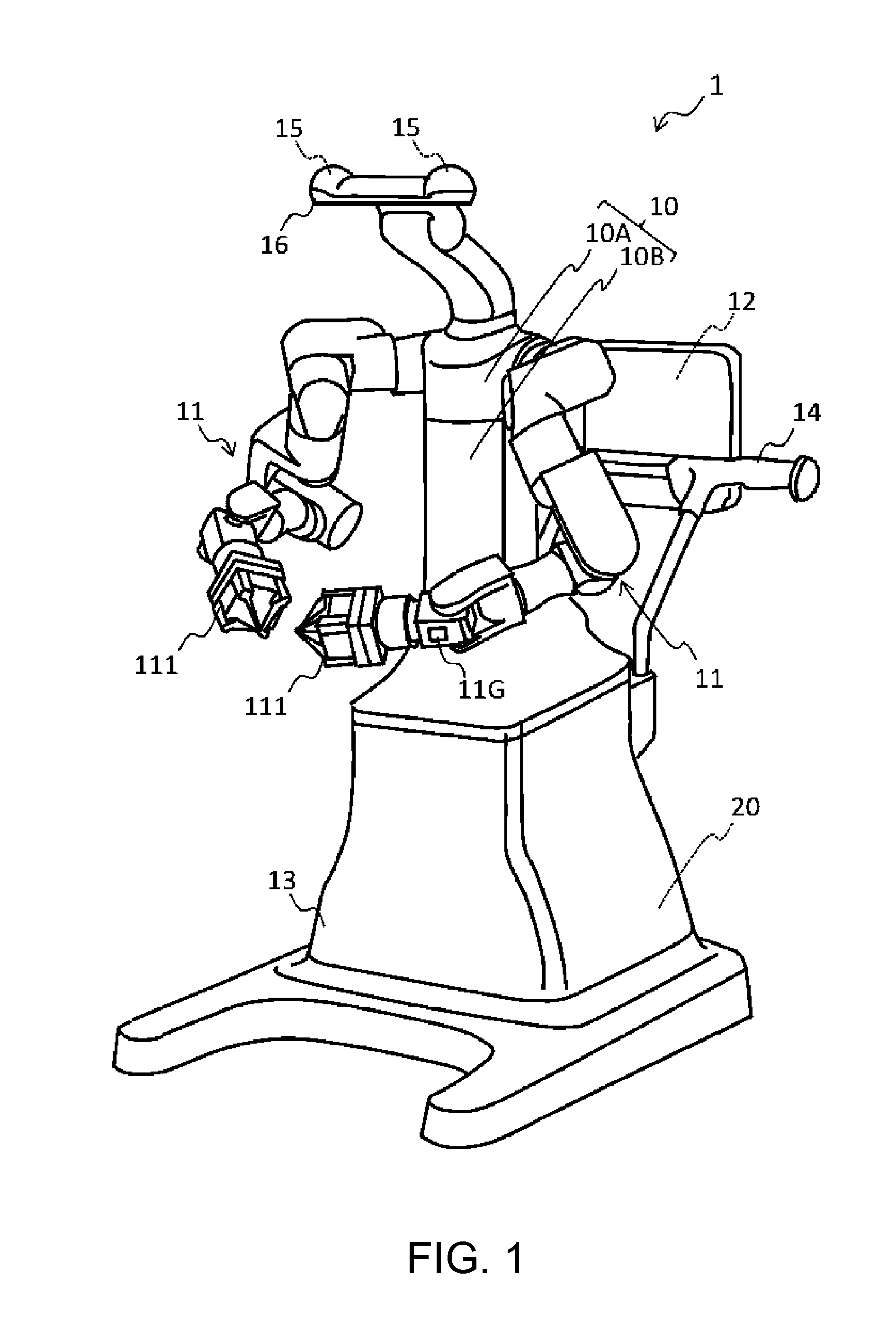
[0045]FIG. 1 is a front perspective view showing an example of a robot 1 according to the embodiment of the invention. FIG. 2 is a rear perspective view showing an example of the robot 1.

[0046]The robot 1 includes a body section (a trunk section) 10, arms 11, a touch panel monitor 12, a leg section 13, a conveying handle 14, cameras 15, a signal lamp 16, a power switch 17, an external interface (I / F) unit 18, and a lifting and lowering handle 19. The robot 1 is a human type double-arm robot and operates according to control by a control unit 20 (see FIG. 4). The robot 1 can be used in a manufacturing process for assembling a precision instrument such as a printer. Note that this manufacturing work is usually performed on a workbench (not shown in the figure).

[0047]The body section 10 is provided on a frame of the leg section 13. Note that the leg section 13 is a base of the robot 1. The body secti...


PUM


Abstract

A robot includes, a holding unit configured to hold an object, an image pickup unit, and a predetermined first portion of the robot. The image pickup unit picks up images of the holding unit and the object using the first portion as a background.

Description

BACKGROUND[0001]1. Technical Field[0002]The present invention relates to a robot, a robot system, and a robot control apparatus.[0003]2. Related Art[0004]In recent years, in manufacturing sites and the like, scalar robots, multi-axis robots, and the like are used for assembly, inspection, and the like of products. When a robot carries an object in performing assembly or inspection of a product, the robot attracts the object or grips the object with an arm.[0005]In automatic assembly and other work processes, such an industrial robot is requested to efficiently grasp, in a predetermined posture, a target object that takes unspecified various postures. In the industrial robot, a driver is attached to an end effector of the robot. The industrial robot automatically performs screwing in place of a human. In performing the screwing, the industrial robot recognizes the position and the shape of a screw through image processing.[0006]For example, an image processing apparatus is disclosed ...

Claims


Application Information

Patent Timeline
Patent Type & Authority Applications(United States)
IPC IPC(8): B25J9/16
CPCB25J9/1697Y10S901/09Y10S901/41Y10S901/47G05B2219/37208G05B2219/37555G05B2219/39107G05B2219/39109G05B2219/40072G05B2219/40087G05B2219/40609G05B2219/40615G05B2219/45203
Inventor YAMAGUCHI, YUKIHIRO
Owner SEIKO EPSON CORP
Why Eureka
Try Eureka