
Portable rotary table for radiology department

A portable, rotating table technology, applied in the field of medical devices, can solve the problems that doctors cannot independently control the patient's rotation angle, affect the quality of inspection, and low inspection efficiency, so as to improve inspection efficiency, improve safety, and facilitate operation.

Inactive Publication Date: 2021-04-06
太和县人民医院
View PDF0 Cites 0 Cited by
  • Summary
  • Abstract
  • Description
  • Claims
  • Application Information

AI Technical Summary

Problems solved by technology

[0003] When a doctor performs a perspective examination on a patient, the doctor needs to let the patient rotate his body position at any time so that the doctor can perform a more accurate examination, and at present this rotation can only be performed by the patient himself, and the doctor cannot control the rotation angle of the patient independently. As a result, the inspection efficiency is very low and the inspection quality is affected. Therefore, in view of the above status quo, it is urgent to develop a portable rotary table for radiology to overcome the shortcomings in current practical applications.

Method used


Image

  • Portable rotary table for radiology department
  • Portable rotary table for radiology department
  • Portable rotary table for radiology department

Examples


Embodiment 1

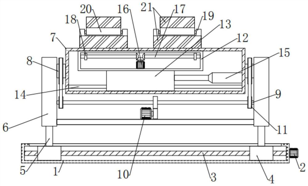
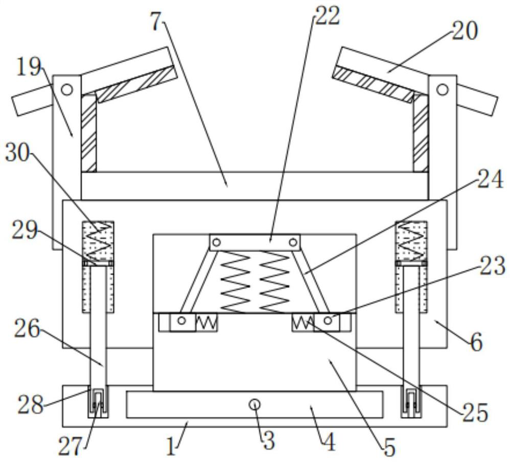
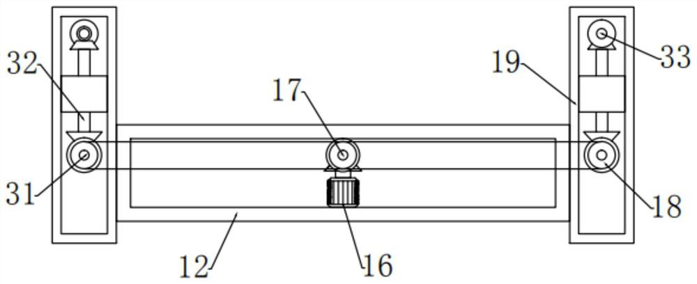
[0025] see Figure 1-4 , in an embodiment of the present invention, a portable rotary table for radiology, including a base 1, a bed board 7 is arranged on the upper side of the base 1, the bed board 7 is connected to the base 1 through a support mechanism, and the support mechanism The inside is provided with an adjustment mechanism, and the left and right sides of the bed board 7 are provided with protection mechanisms, and the protection devices are connected with the control mechanism arranged on the inside of the bed board 7 .

Embodiment 2

[0027] In this embodiment, the support mechanism includes a first motor 2 that is bolted and arranged on the outside of the base 1, the output end of the first motor 2 is connected to a threaded rod 3 that is rotatably arranged on the inside of the base 1, and the threaded rod 3 Located on the inside of the base 1, the front and rear ends are screwed and provided with movable blocks 4, the movable blocks 4 are slidably connected to the chute 34 arranged on the inner side of the base 1, and the tops of the movable blocks 4 on both sides are fixedly connected and provided with support plates 5. A movable plate 6 is provided for sliding connection on the outside of the top of the support plate 5, a shock absorbing mechanism is arranged between the support plate 5 and the movable plate 6, and the movable plate 6 is fixedly connected to the front and rear sides of the bed board 7. The connecting rod 8 is rotatably connected, and the lateral position of the bed board 7 can be adjuste...


PUM


Abstract

The invention relates to the technical field of medical instruments, in particular to a portable rotary table for the radiology department. The portable rotary table comprises a base, a bed board is arranged on the upper side of the base and connected with the base through a supporting mechanism, and an adjusting mechanism is arranged on the inner side of the supporting mechanism; protection mechanisms are disposed at the left and right sides of the bed board; the protection mechanisms are connected with a control mechanism disposed at the inner side of the bed board. According to the examination couch, the transverse position of the couch plate can be adjusted by arranging the supporting mechanism, the angle of the couch plate can be adjusted by arranging the adjusting mechanism and utilizing the second motor, a doctor can conveniently adjust the body position of a patient, operation is convenient, and the examination efficiency is improved; by arranging the protection mechanism, the body of a patient can be kept stable through the baffle and the protection plate in the rotating process of the bed plate, it is guaranteed that examination is conducted stably, by arranging the control mechanism, the position of the baffle and the angle of the protection plate can be adjusted, and a doctor can conduct examination conveniently.

Description

technical field [0001] The invention relates to the technical field of medical devices, in particular to a portable rotary table for radiology. Background technique [0002] The Department of Radiology is an important auxiliary examination department of the hospital. In the construction of modern hospitals, the Department of Radiology is a department that integrates inspection, diagnosis, and treatment. Many diseases in various clinical departments must be clearly diagnosed and auxiliary diagnosis through the inspection of radiology equipment. The radiology equipment generally includes ordinary X-ray filming machine, computerized radiography system (CR), direct digital radiography system (DR), computerized tomography (CT), nuclear magnetic resonance (MRI), digital subtraction angiography Angiography system (DSA), etc. [0003] When a doctor performs a perspective examination on a patient, the doctor needs to let the patient rotate his body position at any time so that the d...

Claims


Application Information

Patent Timeline
IPC IPC(8): A61B6/04
CPCA61B6/0407
Inventor 王清弘刘彬马少华习建宁叶晓雨高见
Owner 太和县人民医院
Learn More