
Manufacture of filled aerofoil

a technology of aerofoils and fillings, which is applied in the direction of reaction engines, machines/engines, mechanical apparatuses, etc., can solve the problems of insufficient tolerance, high processing costs, and significant material wastage, so as to improve dimensional tolerance, improve structural properties, and reduce material wastage

Active Publication Date: 2015-05-07
ROLLS ROYCE PLC
View PDF3 Cites 14 Cited by
  • Summary
  • Abstract
  • Description
  • Claims
  • Application Information

AI Technical Summary

Benefits of technology

The patent text describes a method for manufacturing hollow aerofoil components using a plate to cover a pocket, with improved dimensional tolerance, better structural properties and improved cavity filling. A pre-formed filler insert is used to provide support to the capping panel during the permanent joint with the pocketed aerofoil body, resulting in an improved structure that may be stronger and / or lighter than conventional filled aerofoil structures. A foaming pre-formed filler insert is used, which may include a barrier material to prevent contamination of the joint. The pocketed aerofoil body may comprise a step to assist in locating the capping panel and ensuring the finished aerofoil retains its manufactured shape during use. The pre-formed filler insert may also include vibration damping material to reduce the likelihood of damage and failure of the aerofoil component as a result of vibration during use.

Problems solved by technology

Such processes may generate aerofoils with some advantageous properties, such as thin skin thickness and tight dimensional tolerance, but they involve significant material wastage.
This material wastage makes these processes expensive, due at least to high material cost for a given size of hollow aerofoil component.
However, the dimensional, tolerances are not so accurate.
This may be because distortion is introduced in the process of attaching the plate to the pocketed aerofoil, which typically involves local heating at the interface between the plate and the pocketed aerofoil.
Additionally, tolerance errors may “stack-up” in the process used to produce the pocketed aerofoil, the process used to produce the plate, and the process / feature used to locate the plate into position in the pocket, which typically involve placing the plate onto a supporting ledge inside the pocket.
The lack of dimensional accuracy means that the plate generally has to be manufactured to be thicker than would otherwise be required.
Without the extra thickness, the dimensional variation resulting from tolerance “stack-up” and / or distortion may mean that there is not sufficient material to produce the desired aerofoil shape in some of the aerofoils produced by the method.
However, this extra thickness means both that the component is heavier than it would otherwise need to be, and also that there is more material wastage.
Furthermore, to ensure the panels do not bulge due to internal pressure, foaming / expandable materials cannot be used.
Even with judicious positioning of the filling / injection holes, it is not possible to completely fill the internal cavity using such injection.
As such, the type and selection of filler materials which can be used is limited, and materials which may have advantageous properties may be precluded from use in such an injection filling process
As such any internal pocket definition of the aerofoil, such as stiffening ribs, is compromised because of the need to ensure that such features do not obstruct the flow of the filler, which may result in an unacceptable level of fill.
Thus, there may be a delay between activating the pre-formed filler insert and the pre-formed filler expanding, for example to its final size and / or shape.
When the capping panel is located in the capping position, there may be a gap between the pre-formed filler insert and the capping panel.

Method used


Image

  • Manufacture of filled aerofoil
  • Manufacture of filled aerofoil
  • Manufacture of filled aerofoil

Examples


Embodiment Construction

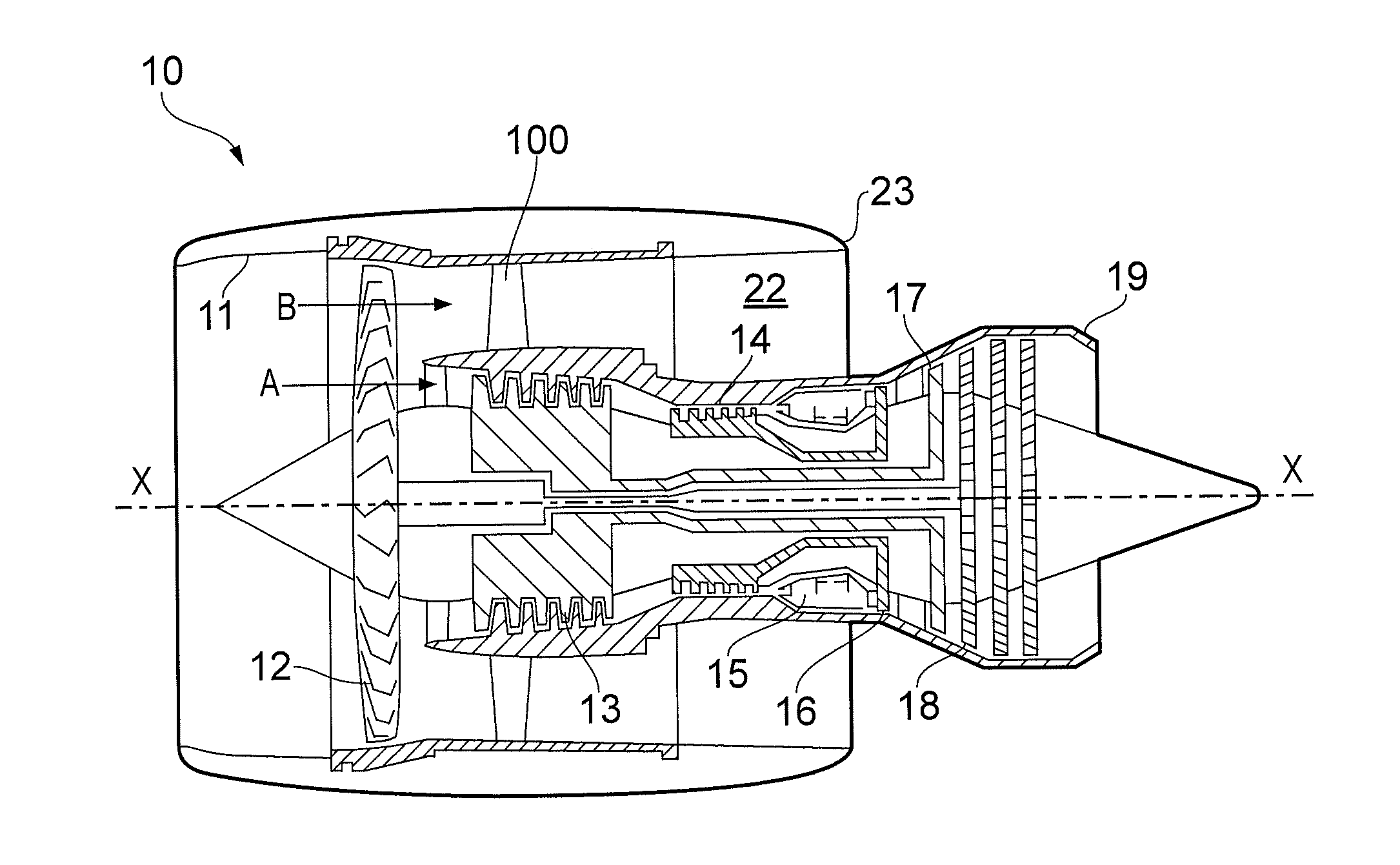
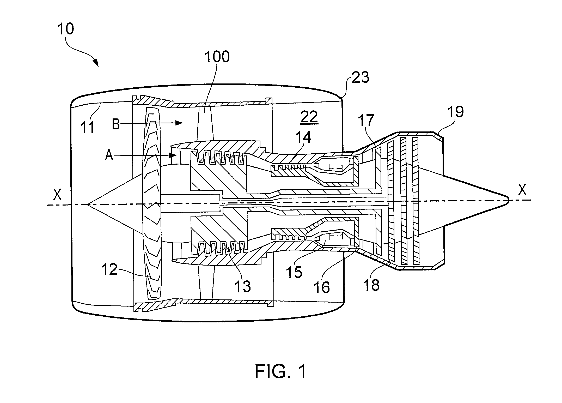
[0053]With reference to FIG. 1, a ducted fan gas turbine engine generally indicated at 10 has a principal and rotational axis X-X. The direction X-X may be referred to as the axial direction of the engine. The engine 10 comprises, in axial flow series, an air intake 11, a propulsive fan 12, an intermediate pressure compressor 13, a high-pressure compressor 14, combustion equipment 15, a high-pressure turbine 16, an intermediate pressure turbine 17, a low-pressure turbine 18 and a core engine exhaust nozzle 19. A nacelle generally surrounds the engine 10 and defines the intake 11, a bypass duct 22 and a bypass exhaust nozzle 23.

[0054]The gas turbine engine 10 works in a conventional manner so that air entering the intake 11 is accelerated by the fan 12 to produce two air flows: a first air flow A into the intermediate pressure compressor 13 and a second air flow B (which may be referred to as a bypass flow B) which passes through the bypass duct 22 to provide propulsive thrust. The i...


PUM

PropertyMeasurementUnit
pressureaaaaaaaaaa
thicknessaaaaaaaaaa
vibration dampingaaaaaaaaaa

Abstract

A method of manufacturing a filled aerofoil component (100) for a gas turbine engine (10) comprises using a capping panel (200) to cover a pocket (310) in a pocketed aerofoil body (300). During manufacture, a pre-formed filler insert (400) is provided to support the capping panel (200) in the correct position. This ensures that the outer surface of the capping panel (200) is located as accurately as possible. This means that the capping panel (200) can be made to be as thin as possible, which in turn reduces weight and material wastage. The pre-formed filler insert (400) provides a lightweight core for the finished aerofoil component in use.

Description

CROSS-REFERENCE TO RELATED APPLICATIONS[0001]This application is based upon and claims the benefit of priority from British Patent Application Number 1316732.5 filed 20 Sep. 2013, the entire contents of which are incorporated by reference.BACKGROUND OF THE INVENTION[0002]1. Field of the Disclosure[0003]The present invention relates to the manufacture of an aerofoil having a filled cavity, in particular the manufacture of an aerofoil component having a filled cavity for use in a gas turbine engine.[0004]2. Description of the Related Art[0005]Aerofoil shaped components are used throughout gas turbine engines. For example, aerofoil shaped stator vanes and rotor blades are used to guide gas through the engine, for example both in the turbine and the compressor, including the fan and associated guide vanes.[0006]Weight reduction is an important consideration in gas turbine engines, particularly, although not exclusively, for gas turbine engines used to power aircraft. Generally, the lowe...

Claims


Application Information

Patent Timeline
Patent Type & Authority Applications(United States)
IPC IPC(8): B23P15/04F01D5/14
CPCB23P15/04F05D2230/60F01D5/147F01D5/18F05D2230/232Y02T50/60Y10T29/49336
Inventor RADOMSKI, STEVEN ALEKSY
Owner ROLLS ROYCE PLC
Learn More