
Seal configuration for a turbo machine

a technology of sealing configuration and turbo machine, which is applied in the direction of machines/engines, stators, liquid fuel engines, etc., can solve the problems of significant damage inside and outside the turbo machine, contact between the rotors, etc., to prevent severe heating of the sealing configuration, reduce the load on the contact area, and prevent overheating or damage to the rotor

Active Publication Date: 2015-05-07
MTU AERO ENGINES GMBH
View PDF4 Cites 0 Cited by
  • Summary
  • Abstract
  • Description
  • Claims
  • Application Information

AI Technical Summary

Benefits of technology

The present invention relates to a seal configuration for a turbo machine that minimizes the risk of damage when extreme operating conditions occur. The seal configuration includes a sealing element that reduces flow losses and prevents excessive heating when the rotor comes into contact with the supporting device. The seal configuration may be used to seal a gap between the rotor and the supporting device, thereby minimizing flow losses and preventing damage to the rotor. The seal configuration includes a self-fluxing nickel alloy that has good mechanical properties such as high corrosion resistance and machinability. The alloy elements boron and silicon are added to lower the melting point of the nickel alloy and prevent overheating or damage to the rotor during under overload conditions.

Problems solved by technology

A failure of the seal caused by extreme operating conditions such as the result of severe deflections of rotor or stator elements may result in contact between the rotor and the retaining or supporting elements of the seal configuration.
This contact may cause significant damage inside and outside the turbo machine, for example as the result of fragments that break off the seal configuration.

Method used


Image

  • Seal configuration for a turbo machine
  • Seal configuration for a turbo machine

Examples


Embodiment Construction

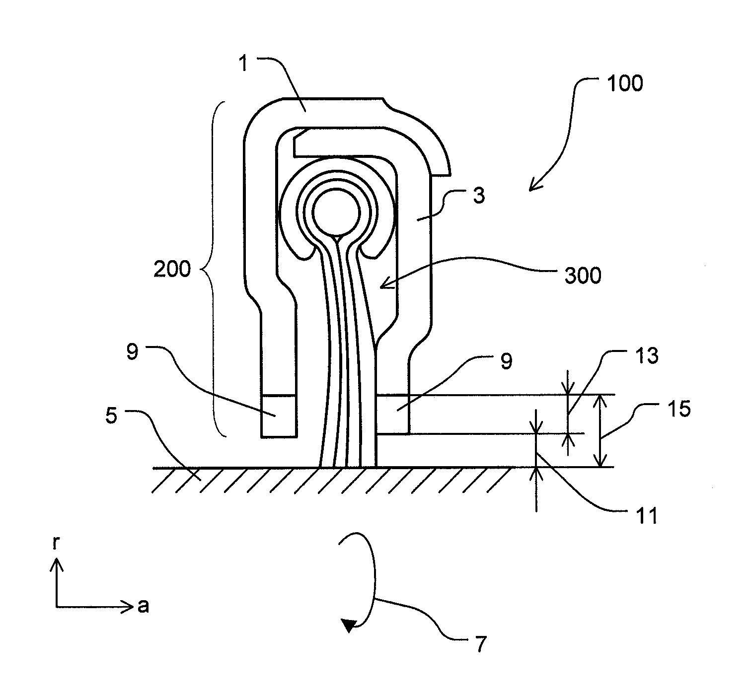
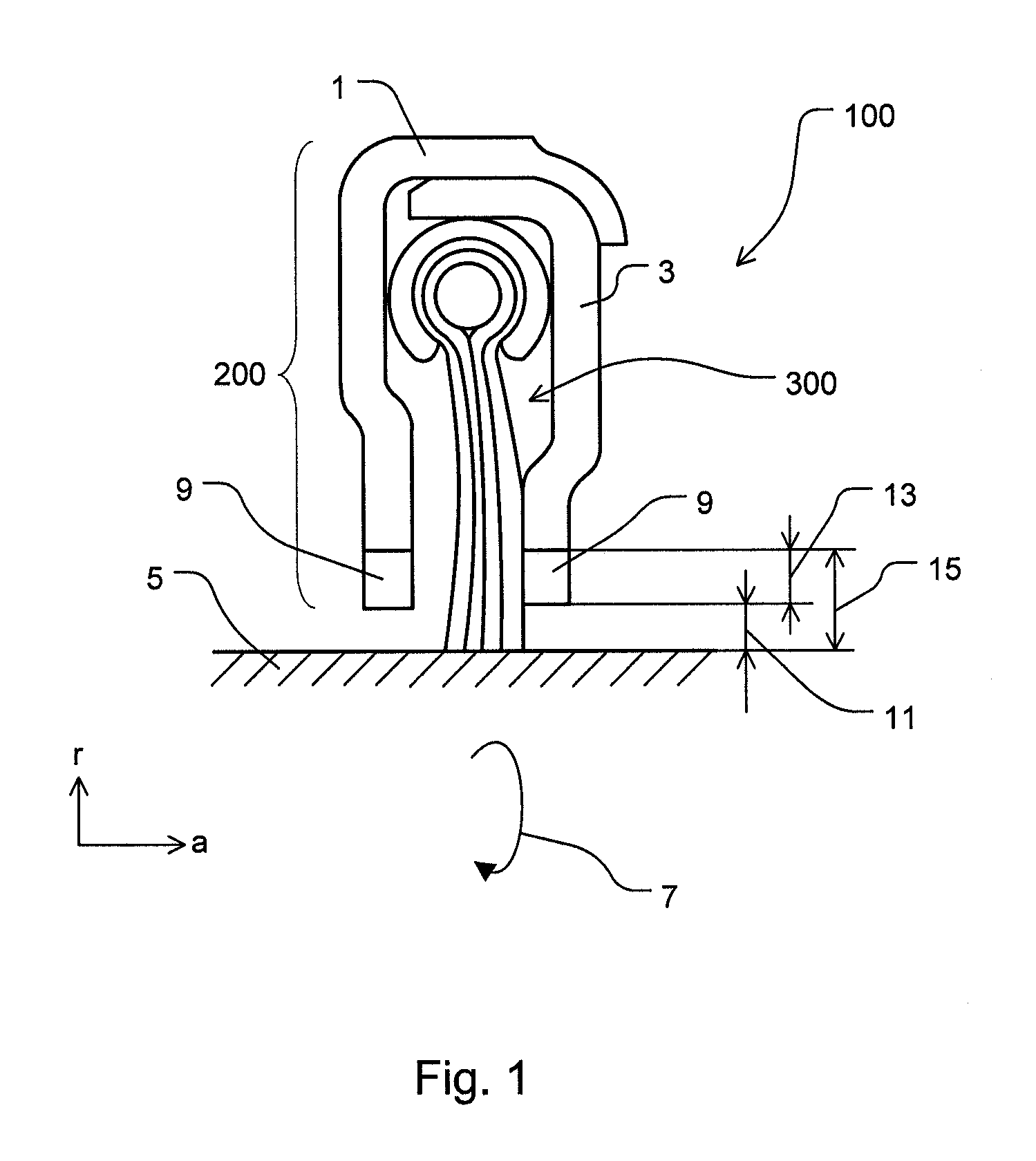
[0039]FIG. 1 shows a seal configuration 100 according to the present invention as an overload rubbing system having a brush seal 300.

[0040]Seal configuration 100 has a supporting device 200 and a sealing element 300 (in this case a brush seal 300). Supporting device 200 has a cover ring 1 and a supporting ring 3. Sealing element 300 is fixed in supporting device 200.

[0041]Seal configuration 100 is arranged in annular fashion around rotor 5. The direction of rotation of the rotor is indicated by arrow 7. Seal configuration 100 or individual areas of it, such as cover ring 1 and / or supporting ring 3, for example, may be segmented over the periphery.

[0042]Seal configuration 100 is situated in particular on the radially inner end of a guide wheel (not shown in FIG. 1).

[0043]Brush seal 300 is fastened or fixed between cover ring 1 and supporting ring 3 with the aid of a mechanical clamp.

[0044]Meltable material 9 according to the present invention is situated on the radially inner end of ...


PUM


Abstract

The present invention relates to a seal configuration (100) for a turbo machine having a rotor (5), wherein the seal configuration (100) has a sealing element (300) to create a seal with respect to the rotor (5) in an installed position and a supporting device (200). The supporting device (200) has, in at least one section of the supporting device, a material (9) that melts when it comes into contact with the rotating rotor (5) in the installed position. The present invention further relates to a turbo machine having a seal configuration (100).

Description

[0001]This claims the benefit of German Patent Application DE 102013222514.8, filed Nov. 4, 2013 and hereby incorporated by reference herein.[0002]The present invention relates to a seal configuration for a turbo machine.BACKGOUND[0003]Different seals, sealing systems and seal configurations are used in turbo machines. Examples include labyrinth seals or contact seals between rotating and static parts, bearing seals or static seals. A failure of the seal caused by extreme operating conditions such as the result of severe deflections of rotor or stator elements may result in contact between the rotor and the retaining or supporting elements of the seal configuration. This contact may cause significant damage inside and outside the turbo machine, for example as the result of fragments that break off the seal configuration.SUMMARY OF THE INVENTION[0004]An object of the present invention is a seal configuration for a turbo machine having a rotor that minimizes the risks and potential da...

Claims


Application Information

Patent Timeline
Patent Type & Authority Applications(United States)
IPC IPC(8): F01D11/00F01D25/00
CPCF01D25/005F01D11/001F01D11/025F05D2240/56F16J15/3288
Inventor WERNER, ANDREKLAEN, STEPHANHERTTER, MANUELSTIEHLER, FRANK
Owner MTU AERO ENGINES GMBH
Learn More