
Systems and methods for establishing and using distributed key servers

a distributed key server and system technology, applied in the field of computer system security, can solve the problems of difficult practical deployment of such a system, inflexibility, defeating the purpose of a distributed system, etc., and achieve the effect of reducing the efficiency or robustness of the cla system against attack and reducing the disadvantages

Inactive Publication Date: 2015-03-26
TORUS VENTURES LLC
View PDF6 Cites 23 Cited by
  • Summary
  • Abstract
  • Description
  • Claims
  • Application Information

AI Technical Summary

Benefits of technology

The patent describes a system for authentication and authorization in a cloud computing environment. It involves a licensing authority (LA) that uses key servers to produce authentication codes for target devices. The system ensures that both the A server and B server must collaborate to produce an authcode for a target device, as the B server cannot produce it alone. This avoids a scenario where the B server could produce an authcode without permission from the A server. Additionally, the system uses a threshold encryption mechanism to increase the efficiency and security of the system against attacks. Overall, the system combines the strengths of a distributed system with the benefits of threshold encryption to securely authenticate and authorize target devices in the cloud.

Problems solved by technology

While this may seem to be the minimal functional arrangement, this situation may lead to a number of difficulties in the practical deployment of such a system.
While this “no new authcodes” limitation may be acceptable in some cases, it is not very flexible.
However, if all of the possible authcodes for the LA are already in existence from the beginning, then once a particular key server has received an authcode for a specific function, then it need never request that specific authcode again, thus defeating the purpose of a distributed system.

Method used


Image

  • Systems and methods for establishing and using distributed key servers
  • Systems and methods for establishing and using distributed key servers
  • Systems and methods for establishing and using distributed key servers

Examples


Embodiment Construction

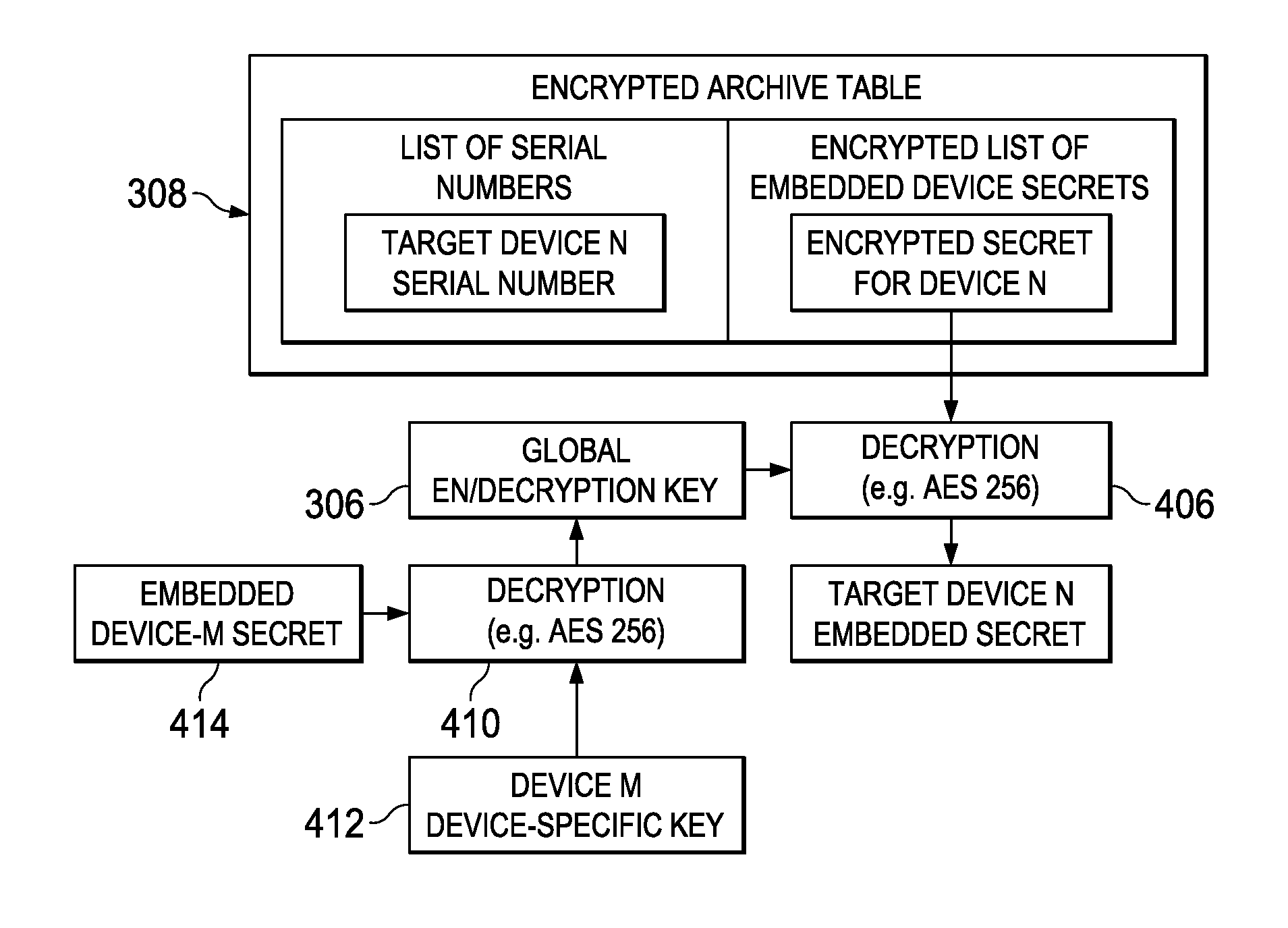
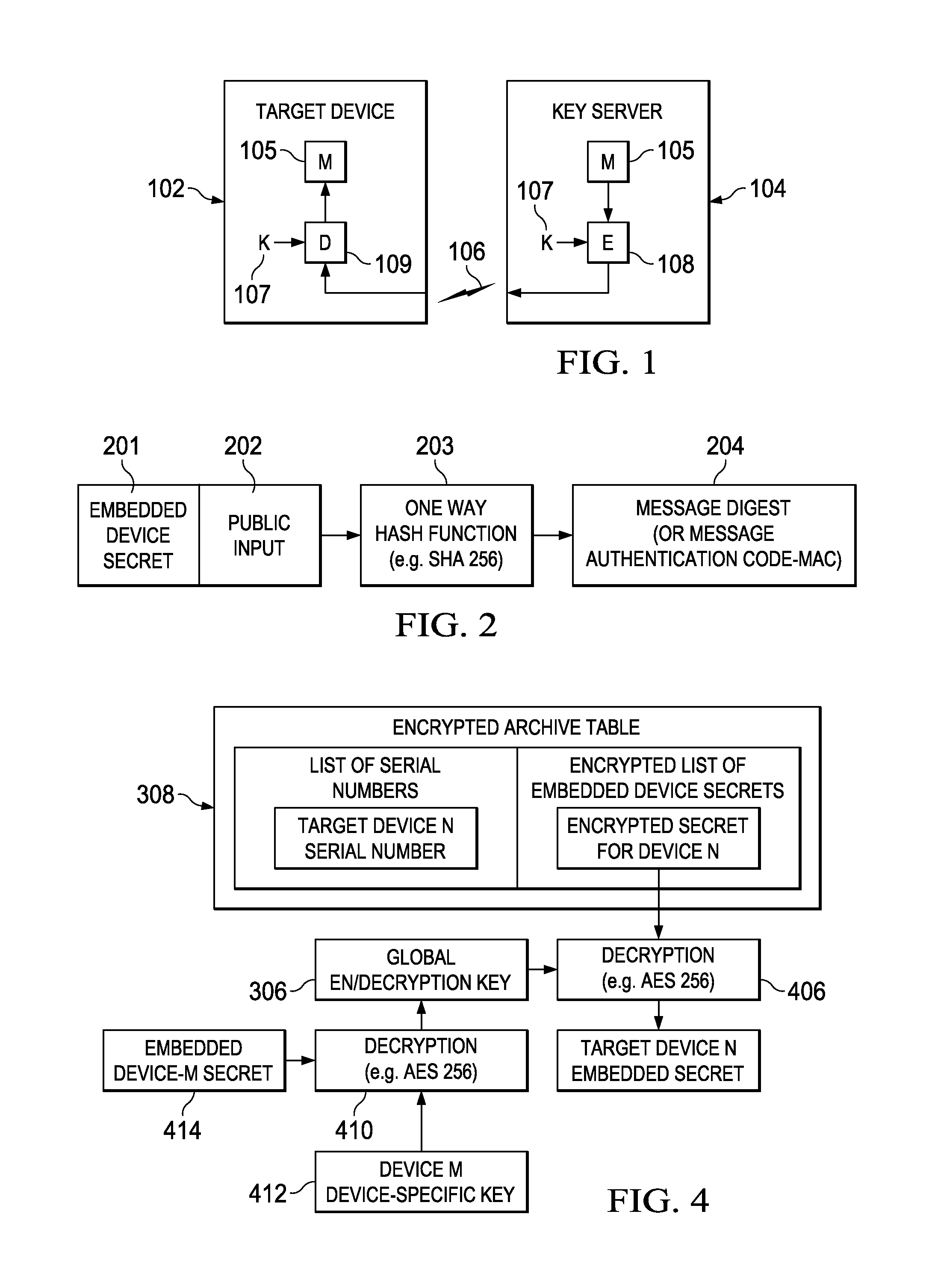
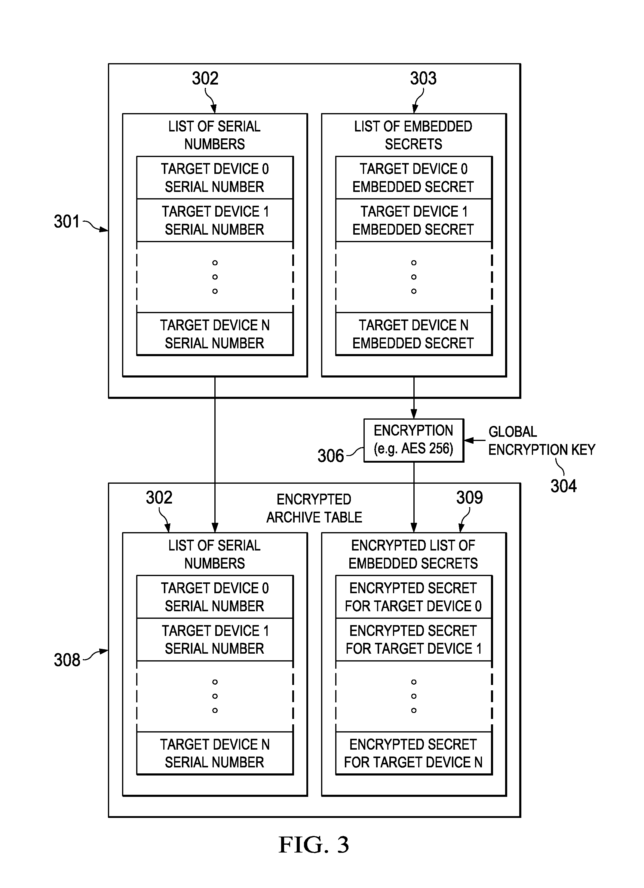
[0038]The invention and the various features and advantageous details thereof are explained more fully with reference to the non-limiting embodiments that are illustrated in the accompanying drawings and detailed in the following description. Descriptions of well-known starting materials, processing techniques, components and equipment are omitted so as not to unnecessarily obscure the invention in detail. It should be understood, however, that the detailed description and the specific examples, while indicating preferred embodiments of the invention, are given by way of illustration only and not by way of limitation. Various substitutions, modifications, additions and / or rearrangements within the spirit and / or scope of the underlying inventive concept will become apparent to those skilled in the art from this disclosure. Embodiments discussed herein can be implemented in suitable computer-executable instructions that may reside on a computer readable medium (e.g., a hard disk or HD...


PUM


Abstract

Systems and methods in which multiple key servers operate cooperatively to securely provide authorization codes to requesting devices. In one embodiment, a server cloud receives a device authorization code request and selects an “A server”. The “A server” requests authorization from one or more “B servers” and authorizes the “B servers” to respond. The “B servers” provide authorization to the “A server”, and may provide threshold key inputs to enable decryption of device authorization codes. The “A server” cannot provide the requested device authorization code without authorization from the “B server(s)”, and the “B server(s)” cannot provide the requested server authorization code and threshold inputs without a valid request from the “A server”. After the “A server” receives authorization from the “B server(s)”, it can provide the initially requested device authorization code to the requesting device.

Description

CROSS-REFERENCE TO RELATED APPLICATIONS[0001]This application claims a benefit of priority to U.S. Provisional Patent Application No. 61 / 882,796, filed Sep. 26, 2013, which is incorporated by reference as if set forth herein in its entirety.TECHNICAL FIELD OF THE INVENTION[0002]This disclosure relates in general to security in computer systems. More specifically, this disclosure relates to systems and methods for securing information associated with processes of a computing system through the use of cooperative key servers.BACKGROUNDRelated Art[0003]A key server is a device that serves cryptographic keys to other devices. The key server and the other devices may be computers that are communicatively coupled via a network such as the Internet. In order to securely distribute a key to a requesting device, it may be necessary that the key server be accessible to a requesting device over a secure connection. That connection may be accomplished via various means, some of which may includ...

Claims


Application Information

Patent Timeline
IPC IPC(8): H04L9/08G06F21/10
CPCH04L9/0819G06F21/105G06F2221/0773H04L2209/603H04L2209/24H04L9/0869H04L2209/60H04L63/062H04L67/1004G06F2221/2145G06F21/107
Inventor OXFORD, WILLIAM V.WOODCOCK, III, GERALD E.
Owner TORUS VENTURES LLC
Learn More