
Asymmetrical detector design and methodology

Active Publication Date: 2015-03-12
KLA TENCOR CORP
View PDF2 Cites 0 Cited by
  • Summary
  • Abstract
  • Description
  • Claims
  • Application Information

AI Technical Summary

Benefits of technology

The present patent is about a charged particle detector and a charged particle optical system. The detector is designed to accommodate an expected asymmetrical distribution of secondary charged particles. It may be shaped like a sector or deposited with an electrically conductive layer. The system includes an active portion of the detector that produces a signal when hit by secondary charged particles. The detector may also have an aperture with an inactive area to reduce signal loss. The charged particle optical system may include an electromagnetic energy beam that passes through the system before impinging on the sample. The detector may be a diode device or a scanning electron microscope. The technical effect of the patent is to improve the efficiency and accuracy of detecting charged particles in various optical systems.

Problems solved by technology

However, since leakage current and capacitance of a detector (e.g., a photodiode) are proportional to the detector area (e.g., the area of the photodiode depletion zone), it is not desirable to have an excessive detector area.
However, while the detector may be rotationally symmetric, the pattern of electrons landing on the detector might not be symmetric.
Thus, conventional detectors require additional process steps that confer additional cost and complexity of alignment or assembly.

Method used


Image

  • Asymmetrical detector design and methodology
  • Asymmetrical detector design and methodology
  • Asymmetrical detector design and methodology

Examples


Embodiment Construction

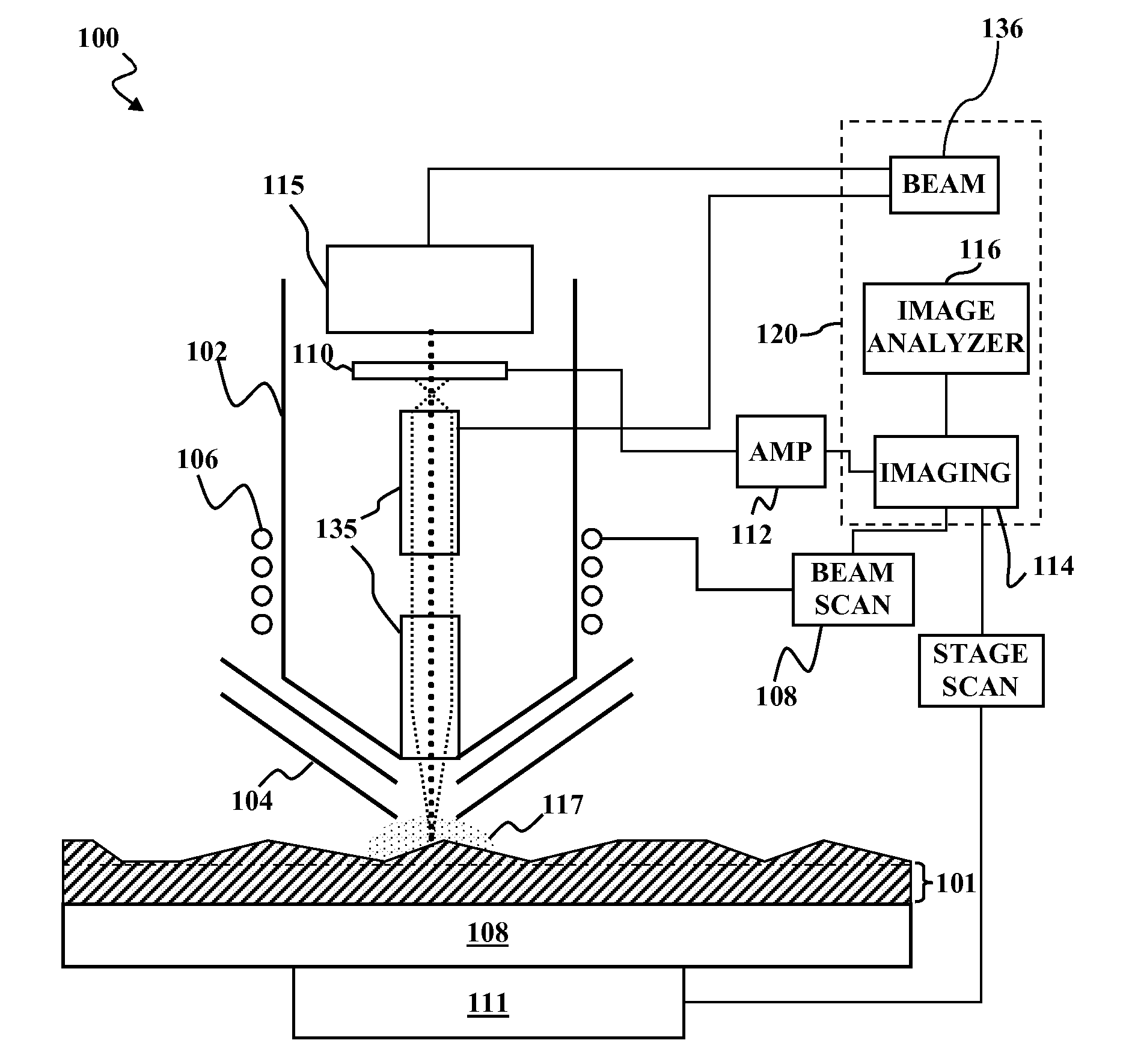
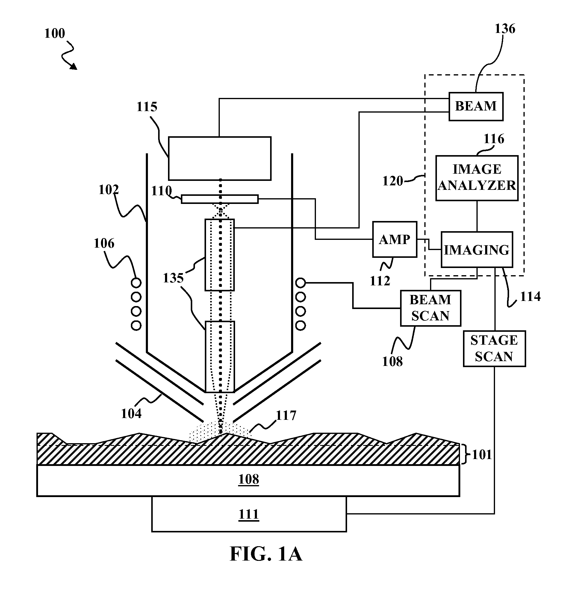
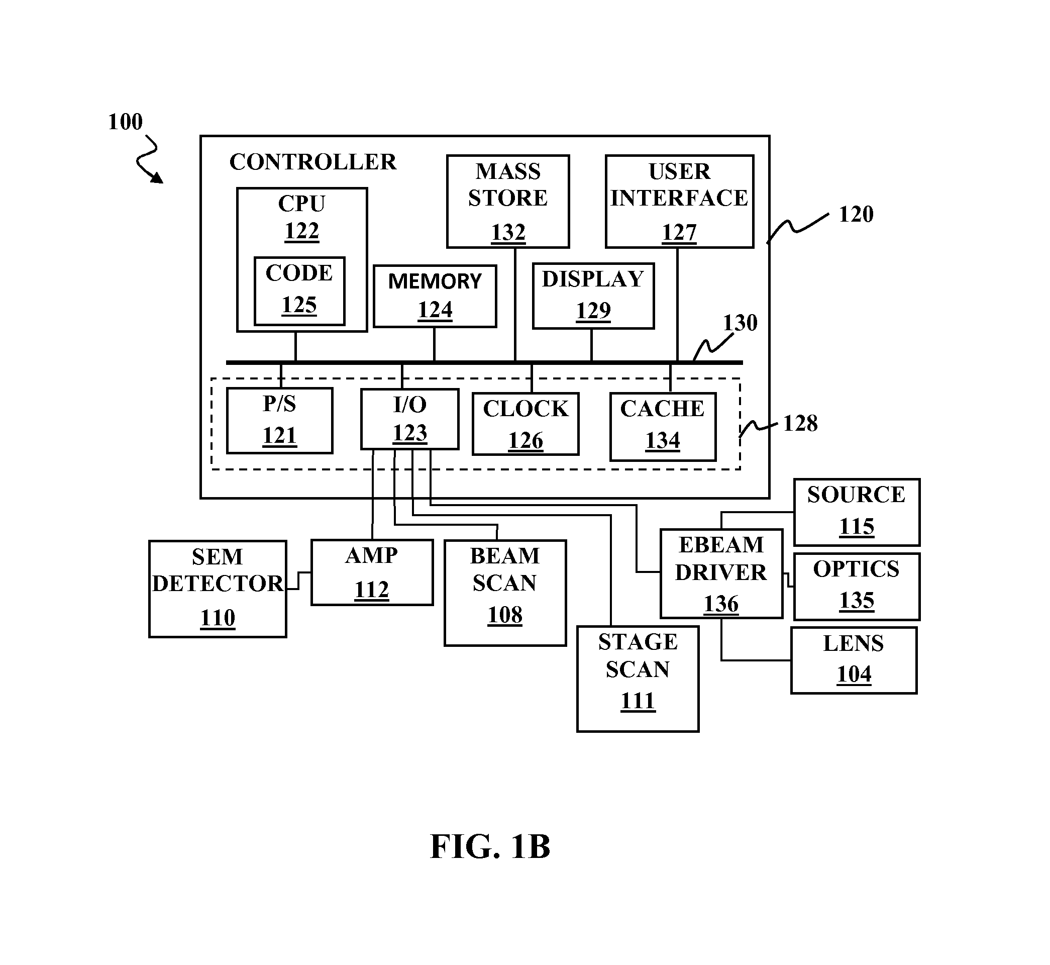
[0032]In the following Detailed Description, reference is made to the accompanying drawings, which form a part hereof, and in which is shown by way of illustration specific embodiments in which the invention may be practiced. The drawings show illustrations in accordance with examples of embodiments, which are also referred to herein as “examples”. The drawings are described in enough detail to enable those skilled in the art to practice the present subject matter. Because components of embodiments of the present invention can be positioned in a number of different orientations, directional terminology is used for purposes of illustration and is in no way limiting. It is to be understood that other embodiments may be utilized and structural or logical changes may be made without departing from the scope of the present invention.

[0033]In this document, the terms “a” and “an” are used, as is common in patent documents, to include one or more than one. In this document, the term “or” i...


PUM


Abstract

A charged particle detection device has an active portion for configured to produce a signal in response secondary charged particles emitted from a sample landing on the active portion. The active portion is shaped to accommodate an expected asymmetric pattern of the secondary charged particles at a detector. This abstract is provided to comply with rules requiring an abstract that will allow a searcher or other reader to quickly ascertain the subject matter of the technical disclosure. It is submitted with the understanding that it will not be used to interpret or limit the scope or meaning of the claims.

Description

CLAIM OF PRIORITY[0001]This application is a nonprovisional of and claims the priority benefit of commonly owned, co-pending U.S. Provisional Patent Application No. 61 / 874,834, to John Gerling et al., filed Sep. 6, 2013, and entitled “ASYMMETRICAL DETECTOR DESIGN AND METHODOLOGY” the entire disclosures of which are incorporated herein by reference.FIELD OF THE INVENTION[0002]Embodiments of the present invention relate to charged particle detection and detection devices, and more particularly, to an optimal detector layout design for secondary charged particle detectors in a charged particle system using multiple columns for line scans.BACKGROUND OF THE INVENTION[0003]Secondary charged particles are emitted from a surface of the specimen to be examined when electron or ion source impinges on the surface with sufficient energy. Since the energy and / or the energy distribution of such secondary charged particles offers information as to the topography of the specimen, detectors are empl...

Claims


Application Information

Patent Timeline
IPC IPC(8): H01J37/28H01J37/20H01J37/14H01J37/22
CPCH01J37/28H01J37/22H01J2237/2801H01J37/14H01J2237/2806H01J37/20H01J37/244H01J2237/2446H01J2237/28
Inventor GERLING, JOHNPLETTNER, TOMASNASSER-GHODSI, MEHRAN
Owner KLA TENCOR CORP
Learn More