
Vehicular lamp unit

a technology of vehicle and lamp body, which is applied in the field of lamps, can solve the problems of reducing the light distribution accuracy of the headlamp, so as to reduce the level of accuracy required for mounting the light-emitting elements on the substrate, reduce the cost required, and facilitate the effect of mounting operation

Active Publication Date: 2015-03-05
KOITO MFG CO LTD
View PDF11 Cites 27 Cited by
  • Summary
  • Abstract
  • Description
  • Claims
  • Application Information

AI Technical Summary

Benefits of technology

The present invention provides a solution to the problem of mounting LEDs on a substrate with high accuracy, as required for headlamps, as it simplifies the operation of mounting light-emitting elements on a substrate. By mounting LEDs at positions close to a reference portion and at positions away from the reference portion, the LEDs located away from the reference portion are less affected by errors in mount position due to deformation of the substrate or attachment to an optical member. This reduces the level of accuracy required for mounting the LEDs on the substrate, making it easier to perform the mounting operation, reducing the cost required for the mounting operation, and reducing the cost for light sources or lamps.

Problems solved by technology

Accordingly, even if light distribution accuracy of the marker lamps reduces due to a small error of the mount positions of the LEDs on the substrate, the reduced light distribution accuracy often falls within an allowable range.
That is, if there is an error of the mount positions of the LEDs on the substrate when the substrate of the light source is attached to an optical member such as a reflector or an illumination lens, this error leads to reduction in light distribution accuracy of the headlamp, and the reduced light distribution accuracy is likely to be out of an allowable range of the headlamp.
In particular, such an error may worsen the light distribution accuracy in an area having high light intensity in the light distribution.
Conventionally, when configuring a light source, that is, when mounting a plurality of LEDs on a substrate, the mounting operation is therefore required to be performed with high accuracy, which makes the mounting operation troublesome.
Moreover, the mounting operation requires skill.
Even if the LEDs are mounted by this method, those LEDs which are mounted at the positions away from the reference hole change in position relative to the reference hole due to thermal deformation etc. of the substrate which occurs after mounting of the LEDs, and this causes an error of the mount positions of the LEDs.
The resultant headlamp thus manufactured does not have light distribution characteristics as designed.
This makes accuracy control in the mounting operation troublesome and difficult, and increases manufacturing cost of light sources or manufacturing cost of lamps.

Method used


Image

  • Vehicular lamp unit
  • Vehicular lamp unit
  • Vehicular lamp unit

Examples


Embodiment Construction

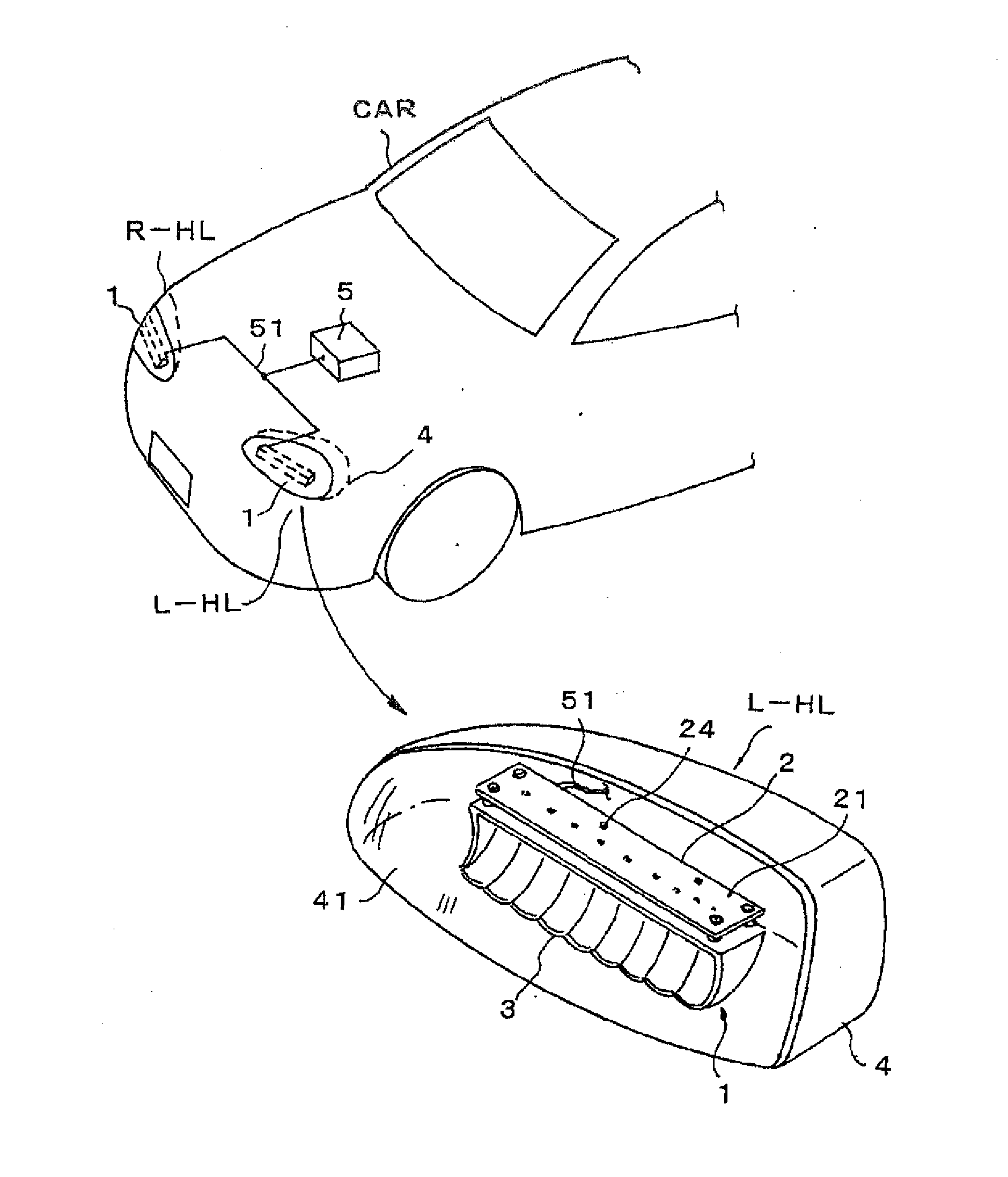
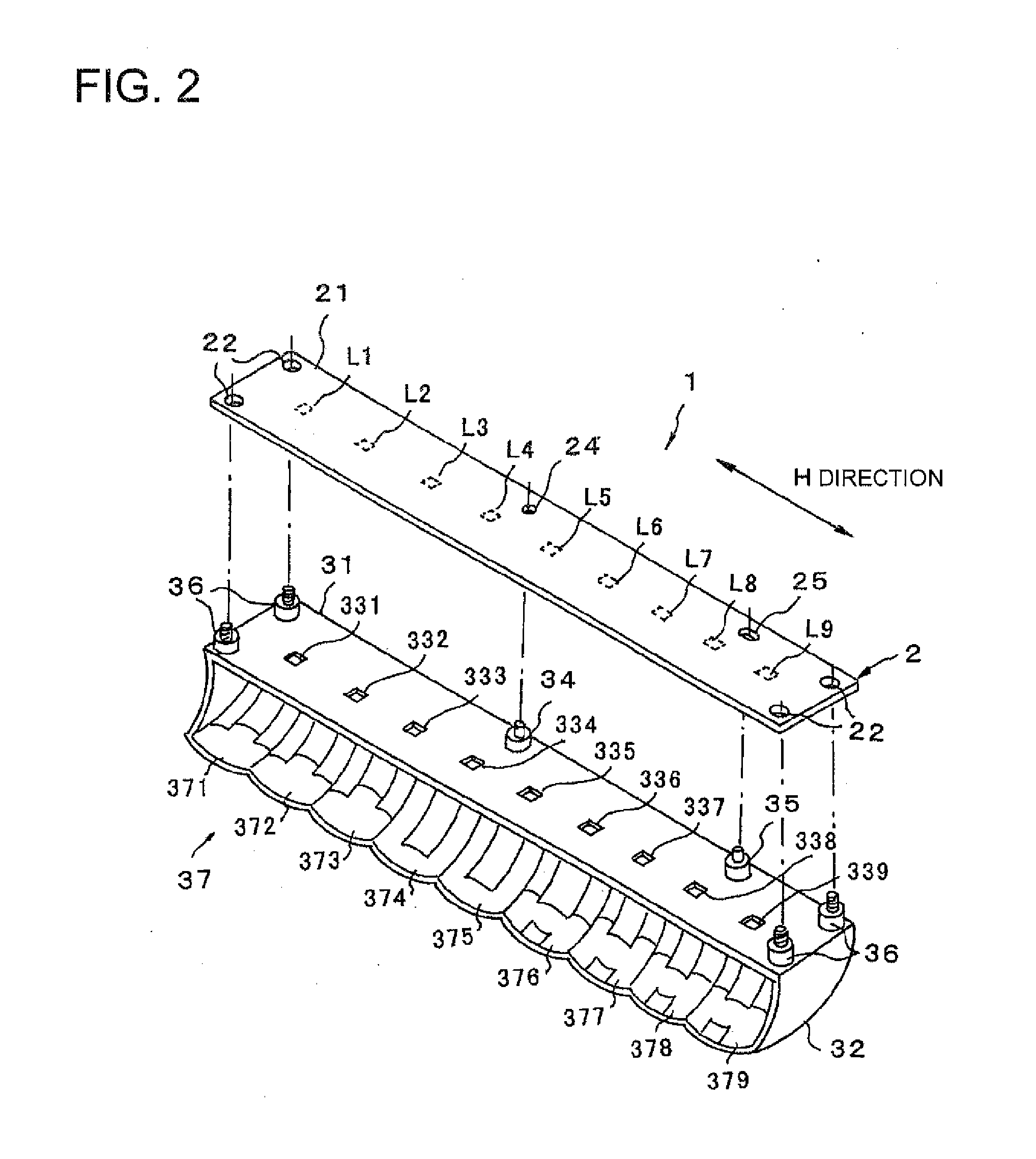
[0020]Embodiments of the present invention will be described with reference to the accompanying drawings. In embodiments of the invention, numerous specific details are set forth in order to provide a more thorough understanding of the invention. However, it will be apparent to one of ordinary skill in the art that the invention may be practiced without these specific details. In other instances, well-known features have not been described in detail to avoid obscuring the invention. FIG. 1 is a perspective view showing a conceptual configuration which a lamp unit according to one or more embodiments of the present invention is applied to headlamps (headlamps) of an automobile. Headlamps L-HL, R-HL are placed on the right and left front parts of a vehicle body of an automobile CAR. In these headlamps L-HL, R-HL, a lamp unit 1 is placed in a lamp housing 4 whose front surface is formed by a translucent cover 41, as a schematic configuration of the left headlamp L-HL is shown in the fi...


PUM


Abstract

A vehicular lamp unit has a substrate, a light source having a first light-emitting element and a second light-emitting element disposed on the substrate, and an optical element having the light source attached thereto. The substrate is long in a first direction. The optical element radiates emitted light of the first and second light-emitting elements toward a front of the vehicular lamp unit, with a desired light distribution. A reference portion serving as a positioning reference for the optical element is provided in a part of the substrate. The first and second light-emitting elements are arranged in the first direction. The first light-emitting element illuminates an area having high light intensity of the light distribution. The second light-emitting element illuminates an area having low light intensity of the light distribution. The first light-emitting element is mounted at a position closer to the reference portion in the first direction than the second light-emitting element.

Description

BACKGROUND[0001]1. Technical Field[0002]The present invention relates to lamps in which a light source is formed by mounting a plurality of semiconductor light-emitting elements such as light-emitting diodes (LEDs) on a substrate, and more particularly to vehicular lamp units that are used for headlamps (headlamps) that form desired light distribution with high accuracy.[0003]2. Related Art[0004]Vehicular lamps such as taillights and headlamps of recent automobiles use semiconductor light-emitting elements such as LEDs as a light source in order to achieve power saving or high durability. For example, Patent Document 1 proposes a turn signal lamp using LEDs as a light source. However, since the amount of light emission of LEDs is smaller than that of bulbs (electric bulbs), a light source is sometimes formed by a plurality of LEDs in order to obtain the amount of light required for the lamp. In Patent Document 1, a plurality of LEDs are mounted on a single substrate, and this substr...

Claims


Application Information

Patent Timeline
Patent Type & Authority Applications(United States)
IPC IPC(8): F21S8/10
CPCF21S48/1104F21S48/1159F21S48/1317F21S41/141F21S41/36F21W2102/00F21W2107/10F21S41/148F21S41/151F21S41/19F21S41/336F21S41/39F21S41/43F21S41/663
Inventor OTSUBO, TAKAYUKI
Owner KOITO MFG CO LTD
Learn More