Techniques for Controlling Vapor Pressure in an Immersion Cooling Tank

a technology of vapor pressure and cooling tank, which is applied in the field of information handling systems, can solve the problems of large expansion space, large heat generation and/or dissipation of servers, and large heat generation during their operation, and achieve the effect of maximizing the effect of expansion on the pressure gradient and avoiding the increase in pressur

Active Publication Date: 2015-03-05
DELL PROD LP
View PDF9 Cites 60 Cited by
  • Summary
  • Abstract
  • Description
  • Claims
  • Application Information

AI Technical Summary

Benefits of technology

This patent describes a system for controlling pressure in an immersion cooling tank. The system includes a cooling mechanism to reduce the temperature of the stored liquid, and a control logic that triggers the inflow valve assembly to increase the flow rate of the liquid and lower its ambient temperature. This increases vapor condensation and reduces the amount of vapor in the tank, thus decreasing the associated pressure. The system also includes a bellows expansion lid that moves upward when the pressure of the rising vapor reaches a certain level, and moves downward when the tank pressure decreases below a certain level. This lid can be positioned close to the tank surface or much smaller, depending on the desired effect on pressure gradient.

Problems solved by technology

These servers can perform significant workloads and generate and / or dissipate a large amount of heat during their operation.
As the need for access to greater and greater processing and storage resources continues to expand, limitations arise surrounding available space for expansion, building and equipment costs, and communication latency.
With the increasing processing and / or storage density in these rack-based server systems, the thermal challenges that result continue to be one of the biggest obstacles.
Conventional fan based cooling systems require large amounts of power, and the cost of power required to drive high flow fans increases exponentially with the increase in server densities.

Method used


Image

  • Techniques for Controlling Vapor Pressure in an Immersion Cooling Tank
  • Techniques for Controlling Vapor Pressure in an Immersion Cooling Tank
  • Techniques for Controlling Vapor Pressure in an Immersion Cooling Tank

Examples


Embodiment Construction

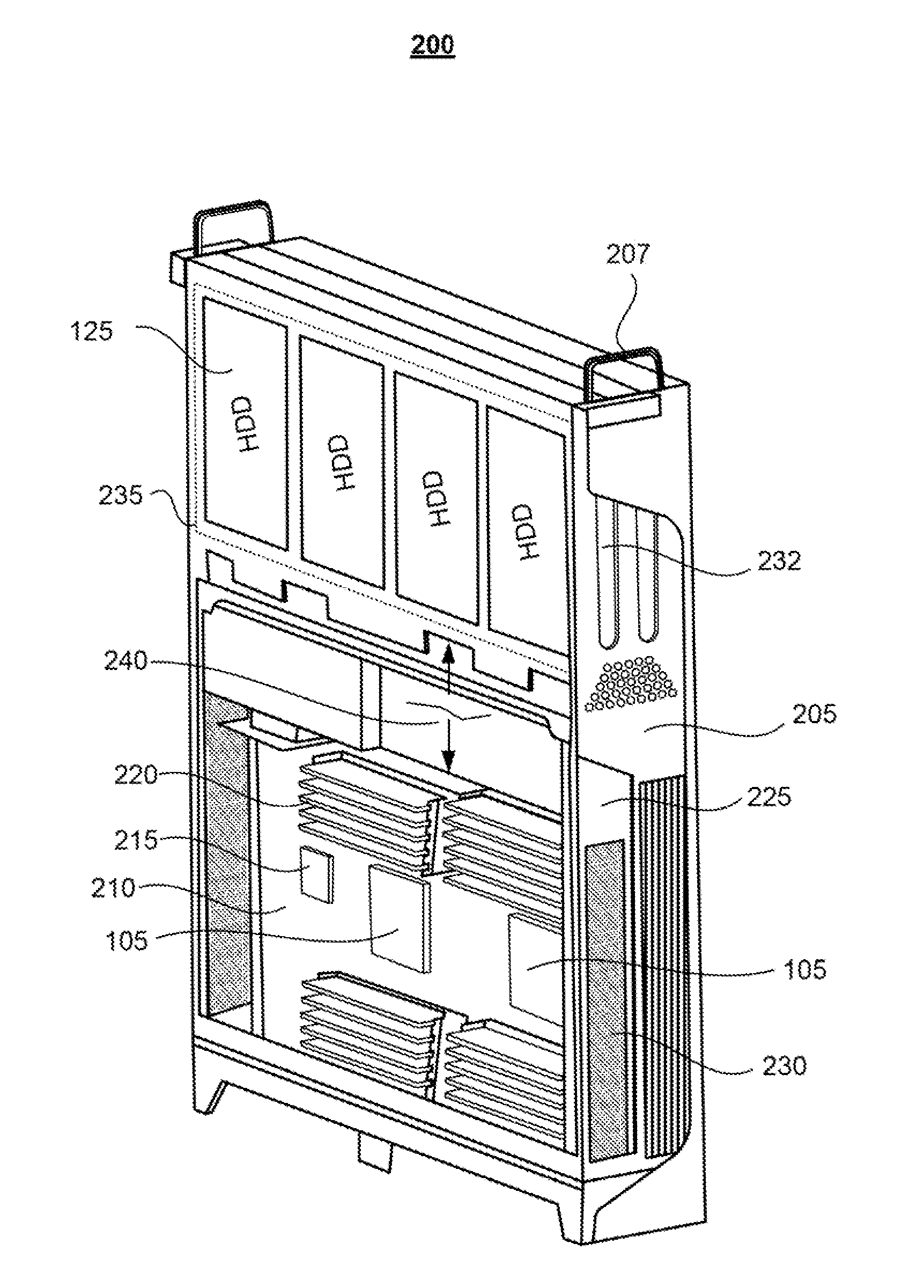
[0043]The present disclosure provides illustrative embodiments of various aspects of and / or different configurations and implementations of one or more systems, methods, and multi-phase heat transfer immersion cooling vessels that enable direct cooling of information handling systems, such as servers, by submerging at least a portion of the physical information handling systems in a dielectric liquid within a multi-phase heat transfer immersion cooling vessel.

[0044]The disclosure generally includes a plurality of different aspects and multiple different embodiments, and each aspect along with the associated embodiments are described in detail below within one of the titled Sections A-K. A first aspect of the general disclosure, presented in Section A, provides examples of an information handling system and of two different servers configured and / or oriented for use within a rack-based immersion cooling system. Section B, which describes the second aspect of the general disclosure, i...


PUM


Abstract

A method that controls pressure within an immersion cooling tank having condensation fluid flowing through a condenser, includes: a controller receiving a signal that indicates a current level of vapor pressure within the tank; determining from the signal when the current level of vapor pressure exceeds or is below a first preset threshold pressure level; and in response to the current level of vapor pressure exceeding or being below the first preset threshold pressure level, signaling a flow control mechanism that modulates a flow rate of the condensation fluid through the condenser to increase or decrease the rate of flow from a current rate of flow. The controller receives the signal by a pressure sensor within the immersion cooling tank detecting the current vapor pressure, generating the signal and forwarding the signal to the controller. The pressure sensor can be a differential pressure transducer that measures a differential pressure internal to and outside of the immersion tank.

Description

BACKGROUND[0001]1. Technical Field[0002]The present disclosure generally relates to information handling systems and in particular to a system and method for cooling of information handling systems that are operated within an immersion cooling vessel. Still more particularly, aspects of the disclosure relate to techniques for managing vapor pressure within an immersion cooling vessel.[0003]2. Description of the Related Art[0004]As the value and use of information continue to increase, individuals and businesses seek additional ways to process and store information. One option available to users is information handling systems. An information handling system generally processes, compiles, stores, and / or communicates information or data for business, personal, or other purposes thereby allowing users to take advantage of the value of the information. Because technology and information handling needs and requirements vary between different users or applications, information handling sy...

Claims


Application Information

Patent Timeline
IPC IPC(8): F28F27/02
CPCF28F27/02G01F1/74H05K7/203H05K7/20809H05K7/20236H05K7/20281
Inventor SHELNUTT, AUSTIN MICHAELCURLEE, JAMES D.
Owner DELL PROD LP
Why Eureka
Try Eureka