Pressure regulating valve

a technology of pressure regulation valve and valve body, which is applied in the direction of fluid pressure control, process and machine control, instruments, etc., can solve the problems of reducing the difficulty of fine adjustment of the opening degree of the opening, and the reduction of the regulation performance of fluid pressure in the pressure regulation chamber. , to achieve the effect of limiting variation in the adjustment accuracy

Inactive Publication Date: 2015-03-05
AISAN IND CO LTD
View PDF2 Cites 7 Cited by
  • Summary
  • Abstract
  • Description
  • Claims
  • Application Information

AI Technical Summary

Benefits of technology

The present invention is a pressure regulating valve that improves the accuracy of fluid pressure adjustment in a pressure regulation chamber. The valve has a device body with an inflow portion, a valve chamber, and an outflow portion. It also has a separating valve seat member, a valve, an urging member, and a piston. The valve can close a first opening and adjust its position based on power supply state. The valve also has a second fluid passage with a different cross-sectional area than the first passage, which draws fluid from the valve chamber to the pressure regulation chamber. A protrusion on the piston or valve can close the second opening when in contact with the other component. The technical effect of this invention is to provide a pressure regulating valve with improved accuracy of fluid pressure adjustment.

Problems solved by technology

In contrast, when the flow rate of gaseous fuel from the valve chamber into the pressure regulation chamber needs to be reduced such as when the set pressure is low or when the fluid pressure in the storage tank is high and the fluid pressure in the valve chamber is high, fine adjustment of the opening degree of the opening is hard to be performed.
This leads to reduction of the regulation performance of the fluid pressure in the pressure regulation chamber.
In this case, this leads to reduction of the regulation performance of the fluid pressure in the pressure regulation chamber.

Method used


Image

  • Pressure regulating valve
  • Pressure regulating valve
  • Pressure regulating valve

Examples


Embodiment Construction

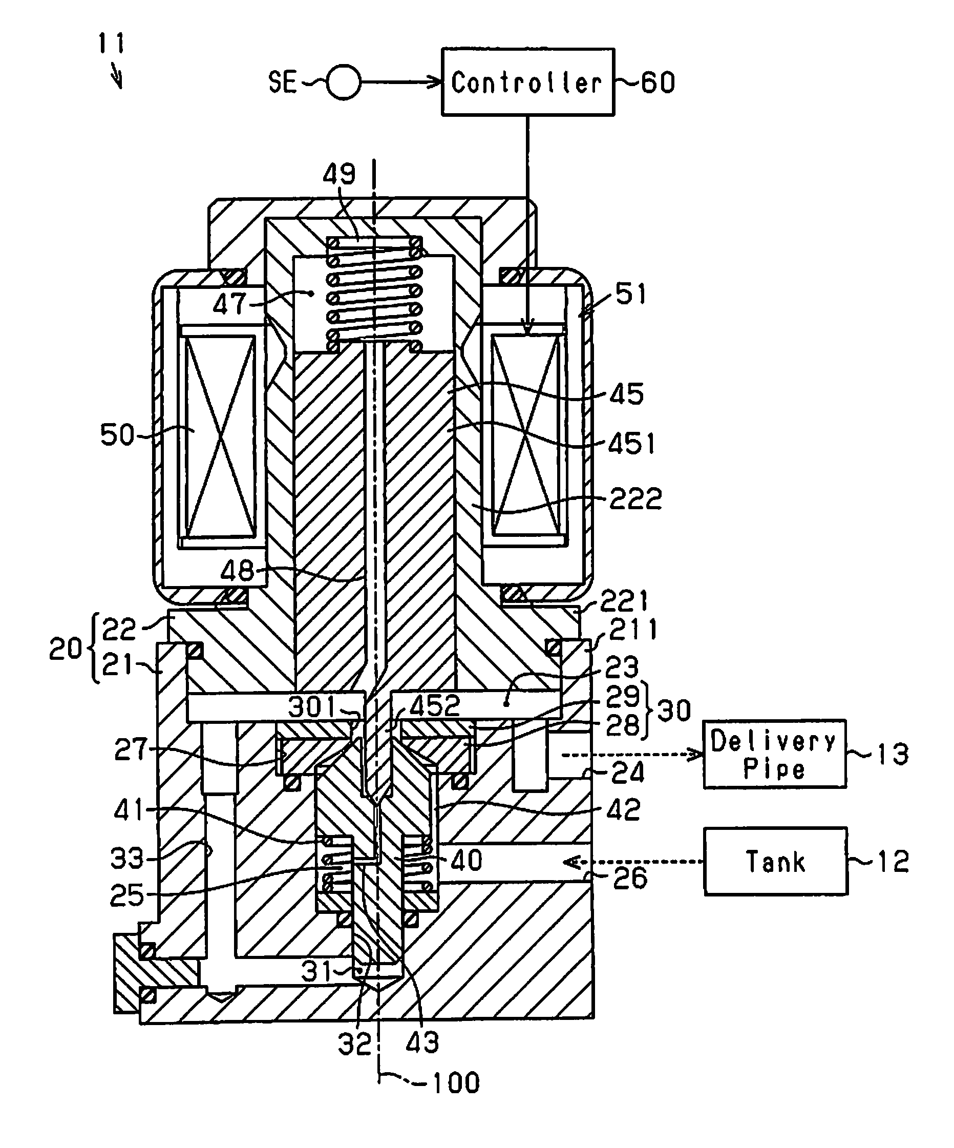
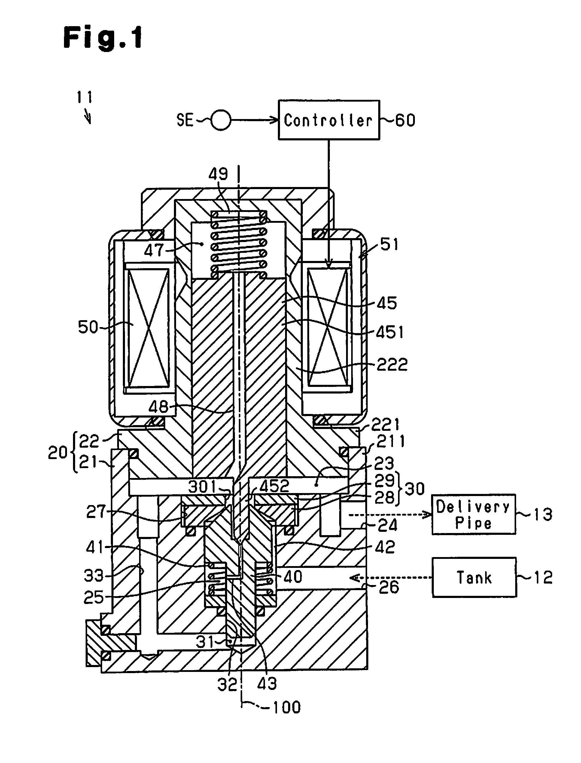
[0022]Hereinafter, a pressure regulating valve that reduces the fluid pressure according to one embodiment will be described according to FIGS. 1 to 6. The vertical direction in FIG. 1 is referred to as axial direction.

[0023]As shown in FIG. 1, a pressure regulating valve 11 is a valve provided in the supply system for supplying compressed natural gas (CNG), which is an example of fluid, to an internal combustion engine. The pressure regulating valve 11 reduces the pressure of CNG at high pressure supplied from a tank 12 and supplies the CNG into a delivery pipe 13. The CNG that is temporarily stored in the delivery pipe 13 is injected through an injector.

[0024]In the internal combustion engine in which the pressure regulating valve 11 according to the present embodiment is provided, the set pressure in the delivery pipe 13 is changed according to the rotation speed of an output shaft. For example, when the output shaft rotates at a high speed such as when the accelerator pedal is o...


PUM


Abstract

A pressure regulating valve includes a device body and an actuator. The device body includes a valve seat member, a valve, which is capable of closing the first opening of the valve seat member, an urging member, which urges the valve toward the valve seat member, a piston arranged opposite to the valve across the valve seat member, an actuator, which adjusts the position of the piston, and a protrusion provided on at least one of the piston and the valve. When the tip end of the protrusion comes into contact with the piston or the valve, the second opening of the second fluid passage is closed. When the tip end of the protrusion is not in contact with any of the piston and the valve and the second opening is opened, the second fluid passage is in communication with the pressure regulation chamber.

Description

RELATED APPLICATIONS[0001]This application claims the benefit of Japanese Patent Application No. 2013-175702, filed Aug. 27, 2013, said application being fully incorporated herein by reference.FIELD OF THE INVENTION[0002]The present invention relates to a pressure regulating valve that reduces the pressure of fluid.BACKGROUND OF THE INVENTION[0003]Convetionally, a pressure regulating valve is provided in a supply system that supplies fluid, which is gaseous fuel for example, to an internal combustion engine. The pressure regulating valve storage reduces the pressure of the gaseous fuel from a high tank pressure to a specified pressure and supplies the gaseous fuel with the reduced pressure to a fuel injection valve, as described in Japanese Laid-Open Patent Publication No. 2012-73886.[0004]The pressure regulating valve disclosed in Japanese Laid-Open Patent Publication No. 2012-73886 includes a valve chamber in communication with an inflow portion, into which the gaseous fuel flows,...

Claims


Application Information

Patent Timeline
Patent Type & Authority Applications(United States)
IPC IPC(8): G05D16/20F02M63/00F16K31/06
CPCG05D16/2006F02M63/0068F02M63/0073F16K31/0655F02M21/023G05D16/028G05D16/2097Y02T10/30Y10T137/7797Y10T137/87515F16K1/52
Inventor KOBAYASHI, MASAHIROHATA, KATSUYUKITAGA, TAKANORI
Owner AISAN IND CO LTD
Why Eureka
Try Eureka