
Engine control for a liquid petroleum gas fueled engine

a technology of liquid petroleum gas and engine control, which is applied in the direction of electric control, machines/engines, output power, etc., can solve the problems of reducing the efficiency of combustion engines. , to achieve the effect of reducing the octane level, increasing the air charge temperature, and increasing the compression ratio

Inactive Publication Date: 2015-03-05
FORD GLOBAL TECH LLC
View PDF21 Cites 18 Cited by
  • Summary
  • Abstract
  • Description
  • Claims
  • Application Information

AI Technical Summary

Benefits of technology

The patent describes a method to prevent combustion knock in a liquid-petroleum gas engine without affecting ignition timing or reducing fuel efficiency. The method involves injecting fuel into the engine cylinders at different times in response to combustion knock detection. This allows for optimal fuel injection and engine performance during wide-open throttle conditions, while also minimizing emissions. Overall, the method improves engine performance and fuel efficiency while preventing combustion knock.

Problems solved by technology

Spark ignition engines may be prone to combustion knock under high loads.
Following spark ignition, areas of the uncombusted air / fuel mixture may self-ignite, causing a large pressure wave that resonates the engine block.
Increased air charge temperatures, increased compression ratios, and lower fuel octane levels may exacerbate the problem.
However, this also has the effect of decreasing fuel economy and deteriorating engine performance during wide open throttle conditions.
Similarly, boosted engines may be prone to cylinder pre-ignition when operating at high load and relatively low engine speed.
Cylinder pre-ignition may manifest as “mega-knock”, producing high-pressure spikes that may damage engine components.
However, this also reduces engine performance.
Gasoline engines utilizing late injection timing may be particularly prone to combustion knock and cylinder pre-ignition.
Late injection of gasoline may cause deposits of soot and / or particulate matter within the cylinder.

Method used


Image

  • Engine control for a liquid petroleum gas fueled engine
  • Engine control for a liquid petroleum gas fueled engine
  • Engine control for a liquid petroleum gas fueled engine

Examples


Embodiment Construction

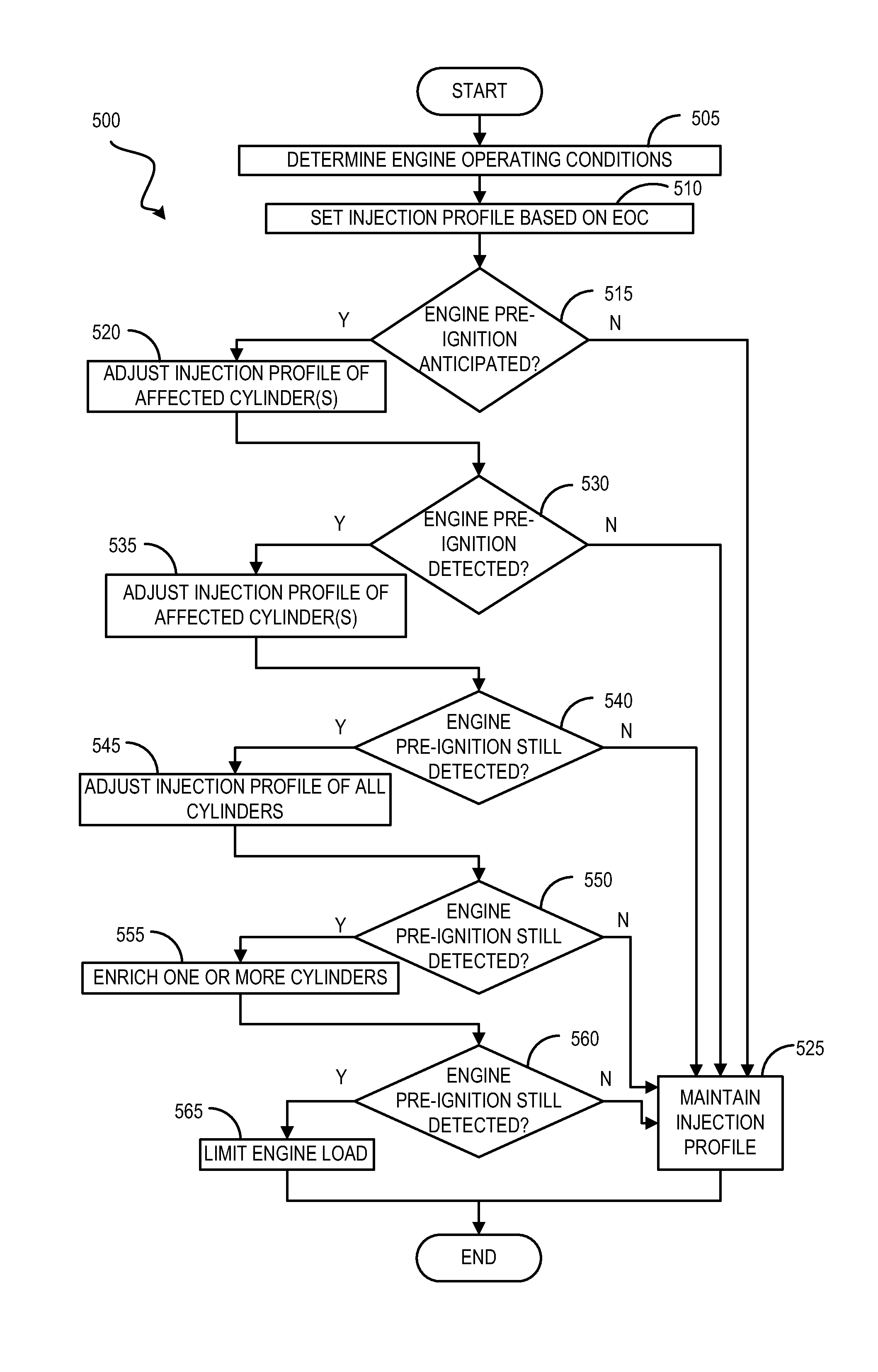
[0017]The following description relates to systems and methods for addressing combustion knock and cylinder pre-ignition in LPG fueled engines, such as the engines schematically diagrammed in FIGS. 1 and 2. The systems may include an LPG fuel tank coupled to a direct-fuel injector. A controller may be programmed to control the rate and timing of fuel injection through a control routine, such as the routines described in FIGS. 3 and 5. In the event of combustion knock, the controller may also be programmed to control spark timing. In the event of cylinder pre-ignition, the controller may also be programmed to control engine load. The timing of fuel injection may be set to coincide with events during the combustion cycle of an engine cylinder, as depicted in FIGS. 4A, 4B, 6A, and 6B.

[0018]FIG. 1 depicts an example embodiment of a combustion chamber or cylinder of internal combustion engine 10. Engine 10 may be controlled at least partially by a control system including controller 12 a...


PUM


Abstract

A method for an engine, comprising: during a first condition comprising a high engine temperature, injecting a first quantity of liquid petroleum gas into a first engine cylinder at a first timing during an intake stroke; and injecting a second quantity of liquid petroleum gas into the first engine cylinder at a second timing during a compression stroke following the intake stroke. In this way, combustion knock and cylinder pre-ignition may be mitigated without retarding spark ignition and / or limiting engine load, thereby allowing for maximum engine performance.

Description

BACKGROUND AND SUMMARY[0001]Spark ignition engines may be prone to combustion knock under high loads. Following spark ignition, areas of the uncombusted air / fuel mixture may self-ignite, causing a large pressure wave that resonates the engine block. Increased air charge temperatures, increased compression ratios, and lower fuel octane levels may exacerbate the problem. A typical method for mitigating engine knock includes retarding the spark ignition timing, thus slowing the combustion burn rate. However, this also has the effect of decreasing fuel economy and deteriorating engine performance during wide open throttle conditions.[0002]Similarly, boosted engines may be prone to cylinder pre-ignition when operating at high load and relatively low engine speed. Cylinder pre-ignition may manifest as “mega-knock”, producing high-pressure spikes that may damage engine components. Cylinder pre-ignition is typically addressed by reducing engine load. However, this also reduces engine perfor...

Claims


Application Information

Patent Timeline
IPC IPC(8): F02D41/30
CPCF02D41/3094F02D41/30F02D41/402F02P5/1522F02D35/027F02D41/0025F02D41/0027F02M21/0284F02D13/0207F02D13/0219F02D19/024F02D19/061F02D19/0647F02D19/0689F02D19/0692F02D19/084Y02T10/30Y02T10/40F02D41/00
Inventor GLUGLA, CHRIS PAULCURTIS, ERIC WARRENSURNILLA, GOPICHANDRAHEDGES, JOHNDEARTH, MARK ALLEN
Owner FORD GLOBAL TECH LLC
Learn More