
Ion Optical System For MALDI-TOF Mass Spectrometer

a mass spectrometer and optical system technology, applied in the direction of instruments, particle separator tube details, separation processes, etc., can solve the problems of limited widespread acceptance, inability to widely use analytical problems, and cost and complexity of these instruments

Active Publication Date: 2015-02-19
VIRGIN INSTR CORP
View PDF12 Cites 35 Cited by
  • Summary
  • Abstract
  • Description
  • Claims
  • Application Information

AI Technical Summary

Benefits of technology

The patent text discusses the different types ofTOF analyzers required for different analytical applications. While combined instruments can save costs, they often result in reduced performance and reliability. The technical effect of the patent is to provide separate instruments for each type of analysis, which improves performance and reliability while minimizing costs.

Problems solved by technology

During the first two decades after the discovery of TOF mass spectrometry, TOF mass spectrometer instruments were generally considered a useful tool for exotic studies of ion properties, but were not widely used to solve analytical problems.
While MALDI-TOF spectrometry technology has been applied to many analytical applications, widespread acceptance has been limited by many factors, including, for example, the cost and complexity of these instruments, relatively poor reliability, and insufficient performance, such as insufficient speed, sensitivity, resolution, and mass accuracy.
However, these combined instruments have the disadvantage of there being a substantial increase in instrument complexity, a reduction in reliability, and other compromises that make the performance of all of the analyzers less than optimal.

Method used


Image

  • Ion Optical System For MALDI-TOF Mass Spectrometer
  • Ion Optical System For MALDI-TOF Mass Spectrometer
  • Ion Optical System For MALDI-TOF Mass Spectrometer

Examples


Embodiment Construction

[0027]Reference in the specification to “one embodiment” or “an embodiment” means that a particular feature, structure, or characteristic described in connection with the embodiment is included in at least one embodiment of the teaching. The appearances of the phrase “in one embodiment” in various places in the specification are not necessarily all referring to the same embodiment.

[0028]It should be understood that the individual steps of the methods of the present teachings may be performed in any order and / or simultaneously as long as the teaching remains operable. Furthermore, it should be understood that the apparatus and methods of the present teachings can include any number or all of the described embodiments as long as the teaching remains operable.

[0029]The present teaching will now be described in more detail with reference to exemplary embodiments thereof as shown in the accompanying drawings. While the present teachings are described in conjunction with various embodimen...


PUM


Abstract

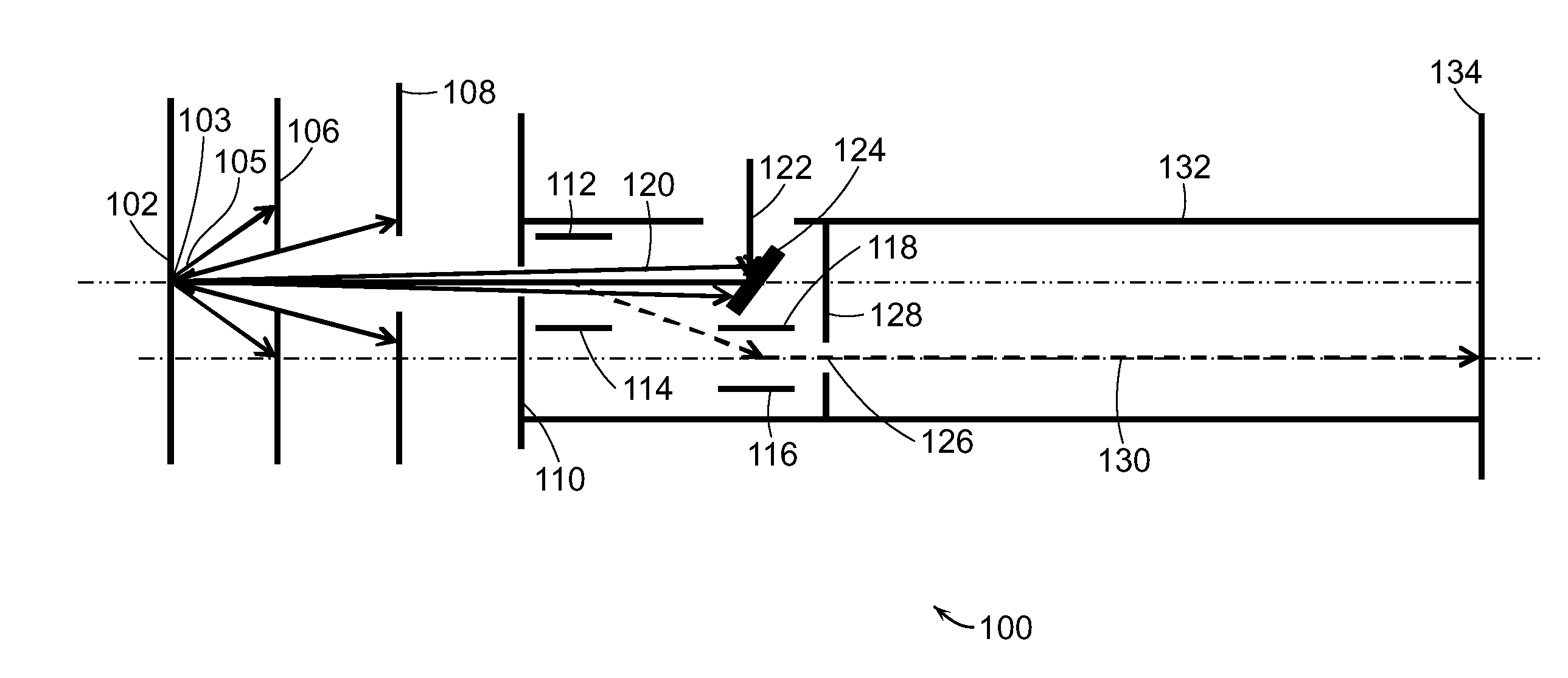
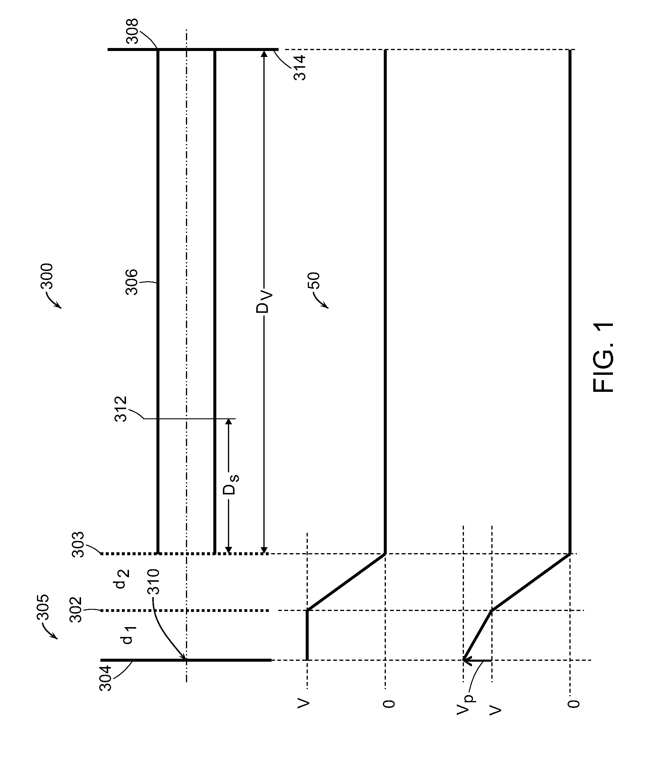
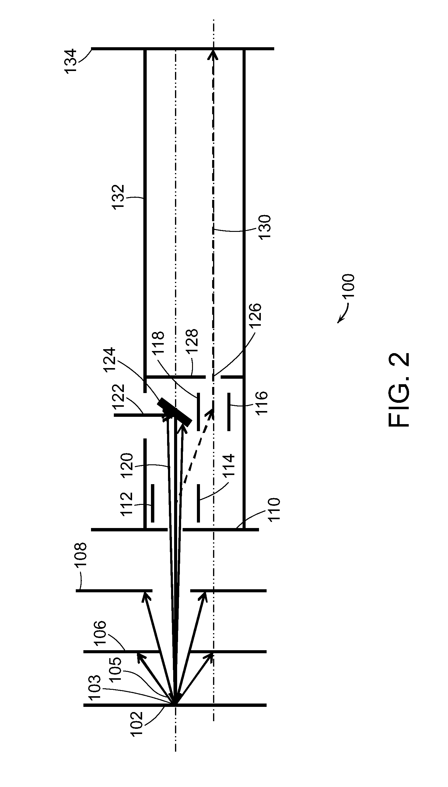
An ion accelerator for a time-of-flight mass spectrometer includes a pulsed ion accelerator positioned proximate to a sample plate and having an electrode that is electrically connected to the sample plate. An accelerator power supply generates an accelerating potential on the ion accelerator electrode that accelerates a pulse of ions generated from the sample positioned on the sample plate. An ion focusing electrode is positioned after the pulsed ion accelerator. A potential applied to the ion focusing electrode focuses the pulse of ions into a substantially parallel beam propagating in an ion flight path. A static ion accelerator is positioned proximate to the ion focusing electrode with an input that receives the pulse of ions focused by the ion focusing electrode. The static ion accelerator accelerating the focused pulse of ions.

Description

CROSS REFERENCE TO RELATED APPLICATION SECTION[0001]The present application claims priority to U.S. Provisional Patent Application No. 61 / 867,375, filed on Aug. 19, 2013, entitled “Mass Spectrometry Method and Apparatus for Diagnostic Applications in a Clinical Laboratory.” The entire content of U.S. Provisional Patent Application No. 61 / 867,375 is herein incorporated by reference.[0002]The section headings used herein are for organizational purposes only and should not to be construed as limiting the subject matter described in the present application in any way.INTRODUCTION[0003]Time-of-Flight (TOF) mass spectrometers are well known in the art. Wiley and McLaren described the theory and operation of TOF mass spectrometers more than 50 years ago. See W. C. Wiley and I. H. McLaren, “Time-of-Flight Mass Spectrometer with Improved Resolution”, Rev. Sci. Instrum. 26, 1150-1157 (1955). During the first two decades after the discovery of TOF mass spectrometry, TOF mass spectrometer instr...

Claims


Application Information

Patent Timeline
IPC IPC(8): H01J49/40H01J49/04H01J49/06
CPCH01J49/403H01J49/0418H01J49/067
Inventor VESTAL, MARVIN L.HAYDEN, KEVIN
Owner VIRGIN INSTR CORP
Learn More