
Process and device for welding a thermoplastic stiffener

a technology of thermoplastic stiffeners and processes, which is applied in the direction of paper/cardboard containers, manufacturing tools, other domestic articles, etc., can solve the problems of reducing the mechanical strength of the matrix, affecting the quality of the product, and the volume of the part heated to this temperature during such an operation must be strictly limited, so as to achieve good insulation and production. the effect of precision and greater precision

Active Publication Date: 2013-04-18
AIRBUS OPERATIONS (SAS)
View PDF3 Cites 7 Cited by
  • Summary
  • Abstract
  • Description
  • Claims
  • Application Information

AI Technical Summary

Benefits of technology

The invention is a device that uses heat to weld parts together. It has a heating plate that is supported by insulating means, which prevents heat from spreading too far. The device is made from a metal with a similar expansion rate to the insulating material, which reduces stress and ensures precise fit between the parts being welded. This minimizes damage to the parts during the welding process.

Problems solved by technology

Under these conditions, the mechanical strength of said matrix is completely reduced, and, if it is not supported, the stiffener is liable to collapse under its own weight, even in the absence of an applied pressure.
Moreover, since thermoplastic polymers have a tendency to expand when heated to their melting point, the volume of a part heated to this temperature during such an operation must be strictly limited, for example by way of tooling, so as to prevent defects appearing in the parts.
Thus, carrying out static welding of a stiffener to a skin, when said stiffener comprises a thermoplastic matrix, requires complex tooling that is expensive to produce and implement.

Method used


Image

  • Process and device for welding a thermoplastic stiffener
  • Process and device for welding a thermoplastic stiffener
  • Process and device for welding a thermoplastic stiffener

Examples


Embodiment Construction

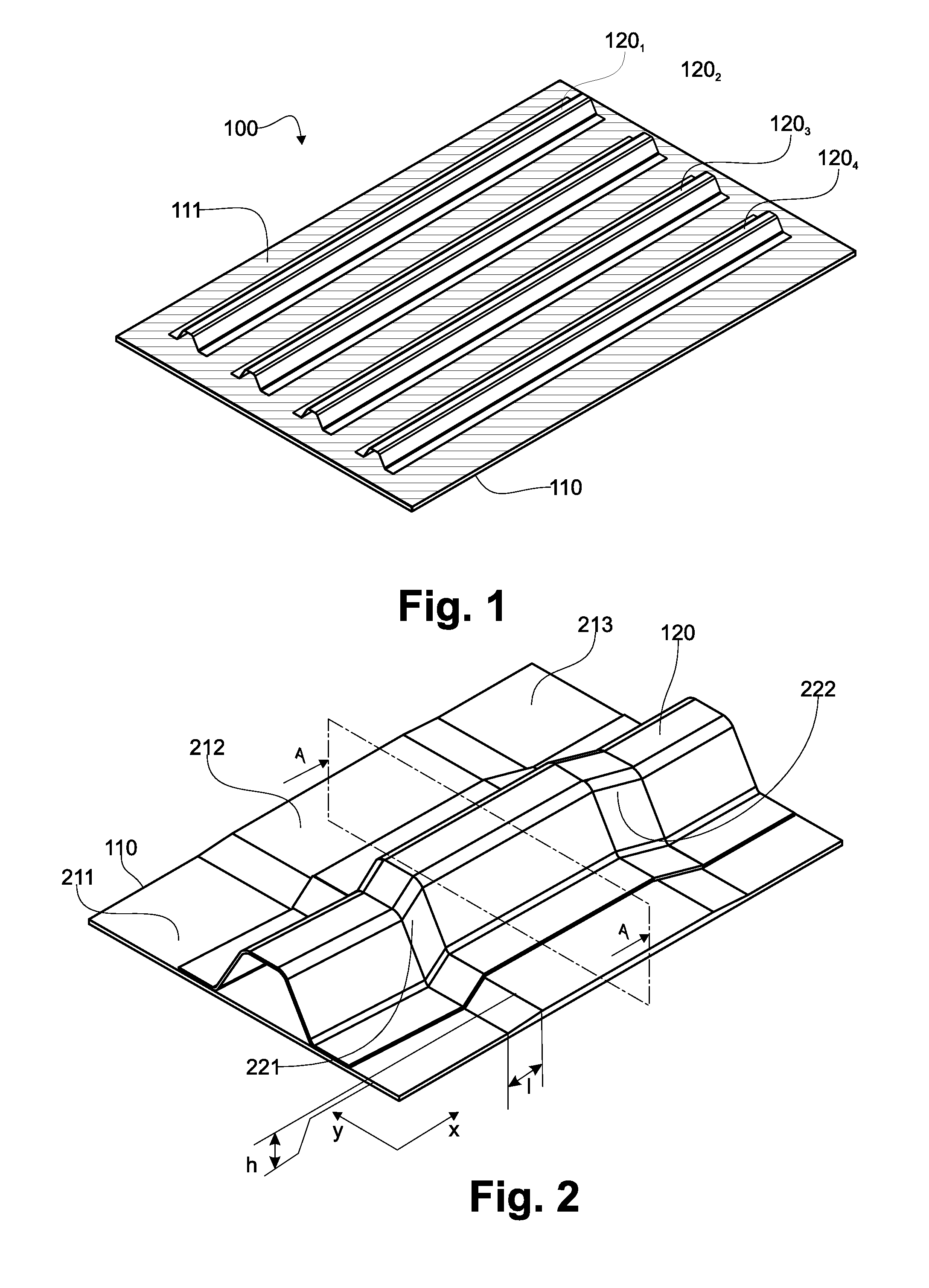
[0045]A stiffened panel (100) consisting of a skin (110) to which stiffeners 1201, 1202, 1203, 1204 have been fixed is shown in FIG. 1. Said stiffeners are fixed so as to bear against one of the sides, called the receiving side (111), of the skin (110).

[0046]According to an exemplary embodiment illustrated in FIG. 2, the skin (110) consists of layers of plies of continuous fibres in a thermoplastic polymer matrix, obtained by draping and compression / consolidation techniques known in the prior art.

[0047]The draping operation may comprise producing ply drop-offs so as to form zones of different thicknesses, forming tiers (211, 212, 213) on either side of the skin (110).

[0048]To ensure load transfer to all the corresponding plies of the thickness reinforcement (212), the ply drop-off zone, i.e. the zone linking two tiers (211, 212), is produced with a taper h / l. Generally said taper is between 0.05 and 0.1.

[0049]According to this embodiment, the stiffener (120) comprises inflections (2...


PUM

PropertyMeasurementUnit
shapeaaaaaaaaaa
pressureaaaaaaaaaa
temperatureaaaaaaaaaa

Abstract

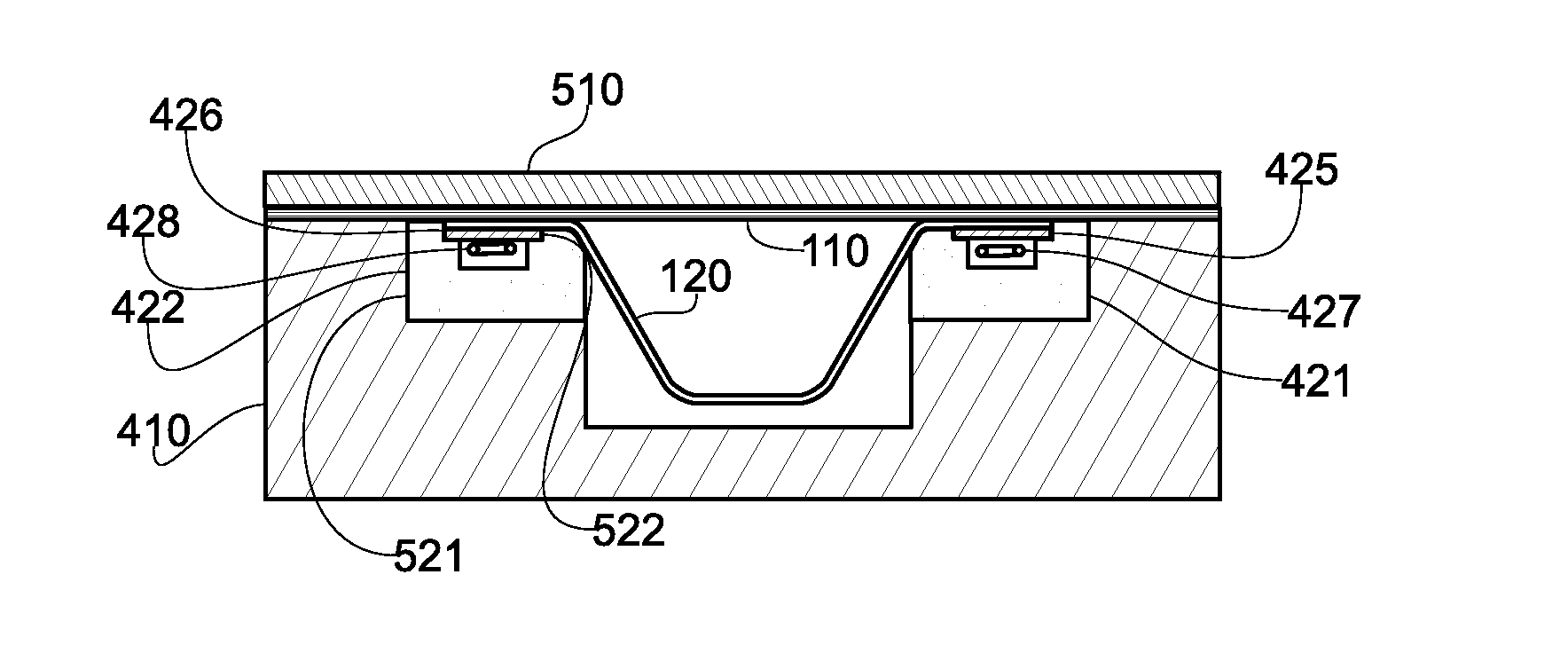
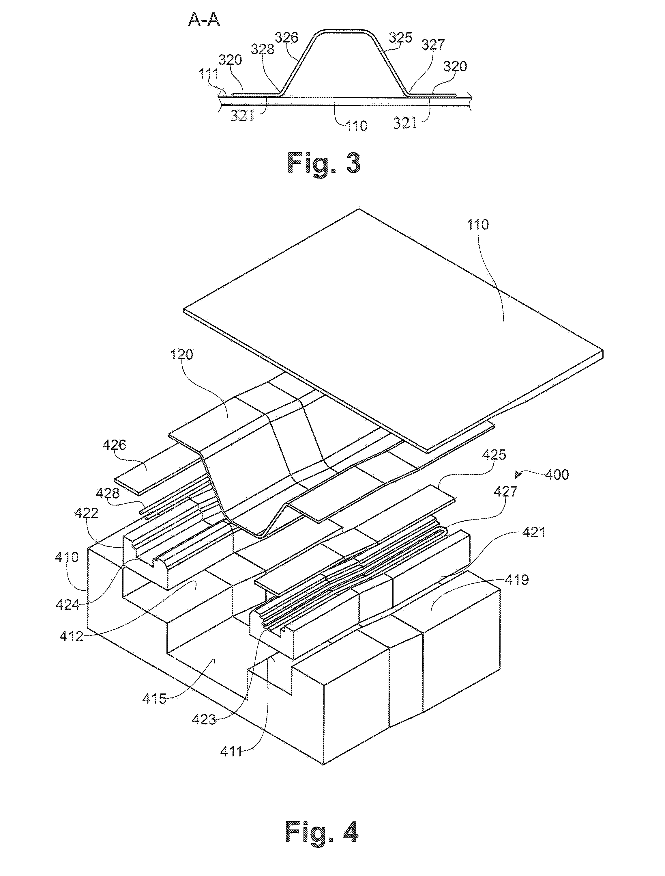
The invention relates to a device for welding a stiffener to a skin. The stiffener has a stiffener foot with a bearing surface parallel to the skin surface and a stiffener flange projecting away from the plane of the bearing surface. The device includes a metallic support includes a seating surface matching the shape of the receiving side; a groove which accommodates a flange of the stiffener inserted in the groove; an insulative supporting structure for positioning a bearing surface against the receiving side; and a conformal panel for applying pressure forcing said bearing surface against said receiving side. A heater temporarily raises the temperature of bearing surface of the stiffener and the adjacent receiving side of the skin to above the melting point of the matrix when pressure is applied thereby welding the stiffener to the skin.

Description

[0001]This application claims priority to FR 20110058945 filed 4 Oct. 2011, the entire contents of each of which are hereby incorporated by reference.BACKGROUND OF THE INVENTION[0002]1. Field of the Invention[0003]The invention relates to a process and a device for welding a thermoplastic stiffener to a skin. The invention more particularly, but not exclusively, relates to the welding of a stiffener and a skin both of which are made of a composite comprising reinforcing fibres in a thermoplastic matrix, the stiffener having an omega-shaped cross section.[0004]2. Description of the Prior Art[0005]The operation for welding a stiffener to a skin, both of which are made of a composite comprising a thermoplastic matrix, requires that at least the interface between the skin and the stiffener be heated to the melting point of the polymer forming the matrix of the skin or stiffener.[0006]Under these conditions, the mechanical strength of said matrix is completely reduced, and, if it is not ...

Claims


Application Information

Patent Timeline
Patent Type & Authority Applications(United States)
IPC IPC(8): B29C65/18
CPCB29C65/18Y10T156/10B29C65/30B29C65/7841B29L2031/003B29C66/1122B29C66/131B29C66/301B29C66/474B29C66/721B29D99/0014B29C66/73921B29C66/8122B29C66/81261B29C66/81419B29C66/81425B29C66/8167B29C66/8432B29C66/91951B29C66/92921B64C1/12B64C2001/0072B29L2031/3076B29C66/92443B29C66/81431B29C66/91945B29C66/91931B29C66/91443B29C65/305Y02T50/433B29C66/91421B29C66/91655B29C66/5346B29C66/91221B29C66/961B29C66/91411B29K2909/02B29K2905/12B29K2903/00B29C66/8322B29C66/7212B29C66/7392B29C66/72141B29C66/81821B29C66/112B29C66/73117Y02T50/40B29C65/245B29K2307/04
Inventor MALASSE, PIERRICCHOTARD, FLORIAN
Owner AIRBUS OPERATIONS (SAS)
Learn More