Coriolis Mass Flow Meter, Vibrating Tube Density Meter and Vibrating Sheet Used Therein
- Summary
- Abstract
- Description
- Claims
- Application Information
AI Technical Summary
Benefits of technology
Problems solved by technology
Method used
Image
Examples
Embodiment Construction
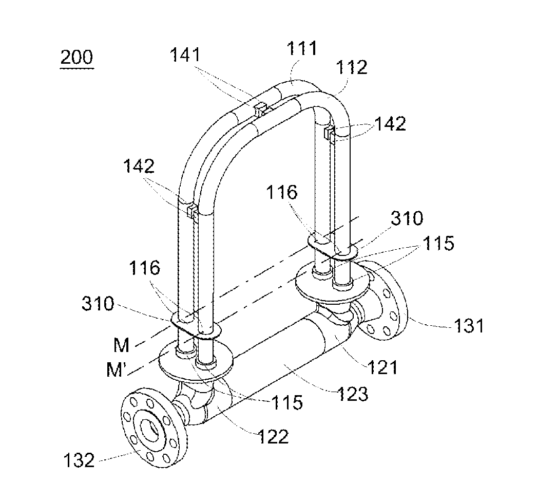
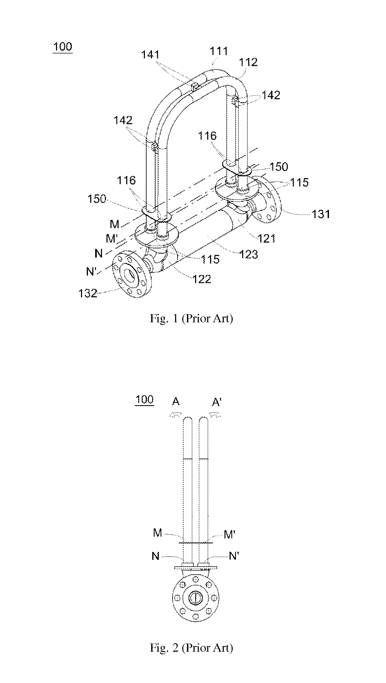
[0064]FIG. 13 is a schematic perspective view of a dual-flow-tube Coriolis mass flow meter or a dual-flow-tube vibrating tube density meter 200 according to one preferred embodiment of the present invention. The entire structure of the Coriolis mass flow meter or the vibrating tube density meter 200 is similar to that of the prior art as shown in FIG. 1. The vibrating sheet 310 also has at least one welded connecting portion that is fixedly welded to the flow tubes 111, 112. The flow tubes 111, 112 are also excited to vibrate around the revolving axes M and M′ at the welded junction of the vibrating sheet 310 and the flow tube. However, in the Coriolis mass flow meter or the vibrating tube density meter 200 of the present invention, the welded connecting portion of the vibrating sheet 310 is only formed in a stress insensitive region of the vibrating sheet. In this embodiment, the stress insensitive region of the vibrating sheet 310 is the region of the circumference of the through ...
PUM
 Abstract
Description
Claims
Application Information
 - R&D
- Intellectual Property
- Life Sciences
- Materials
- Tech Scout
- Unparalleled Data Quality
- Higher Quality Content
- 60% Fewer Hallucinations
Browse by: Latest US Patents, China's latest patents, Technical Efficacy Thesaurus, Application Domain, Technology Topic, Popular Technical Reports.
© 2025 PatSnap. All rights reserved.Legal|Privacy policy|Modern Slavery Act Transparency Statement|Sitemap|About US| Contact US: help@patsnap.com


