Electrolysis cell and electrolysis tank
a technology of electrolysis cell and electrolysis tank, which is applied in the direction of electrolysis components, electrolysis coatings, coatings, etc., can solve the problems of easy cathode oxidation, high cost of electrolysis, and easy cathode degradation
- Summary
- Abstract
- Description
- Claims
- Application Information
AI Technical Summary
Benefits of technology
Problems solved by technology
Method used
Image
Examples
first embodiment
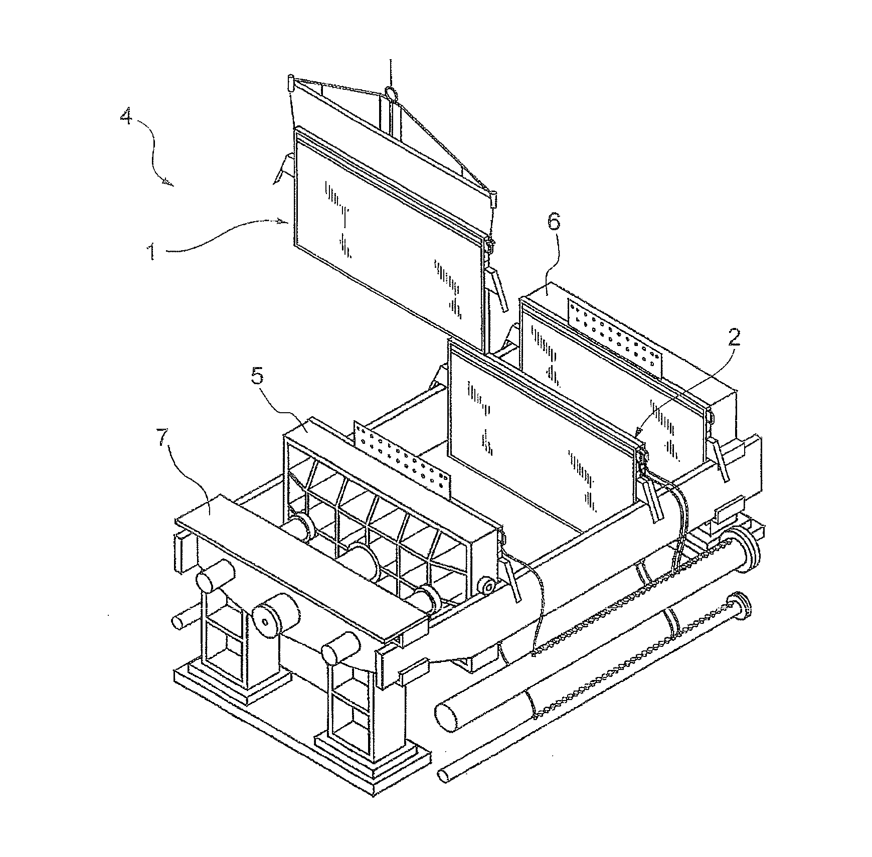
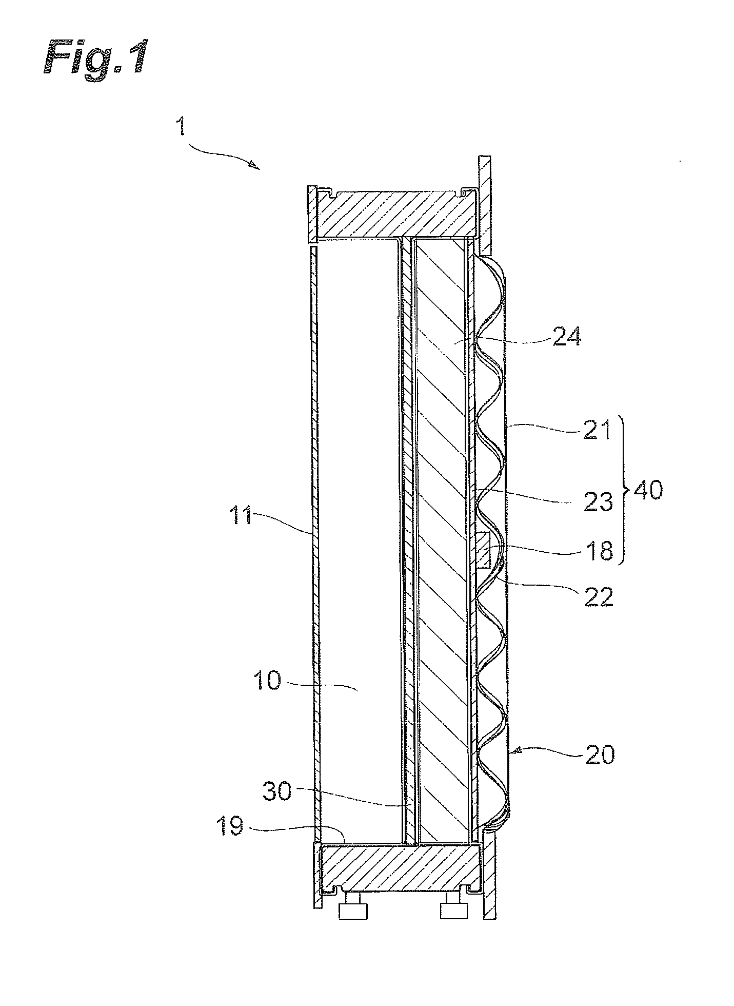
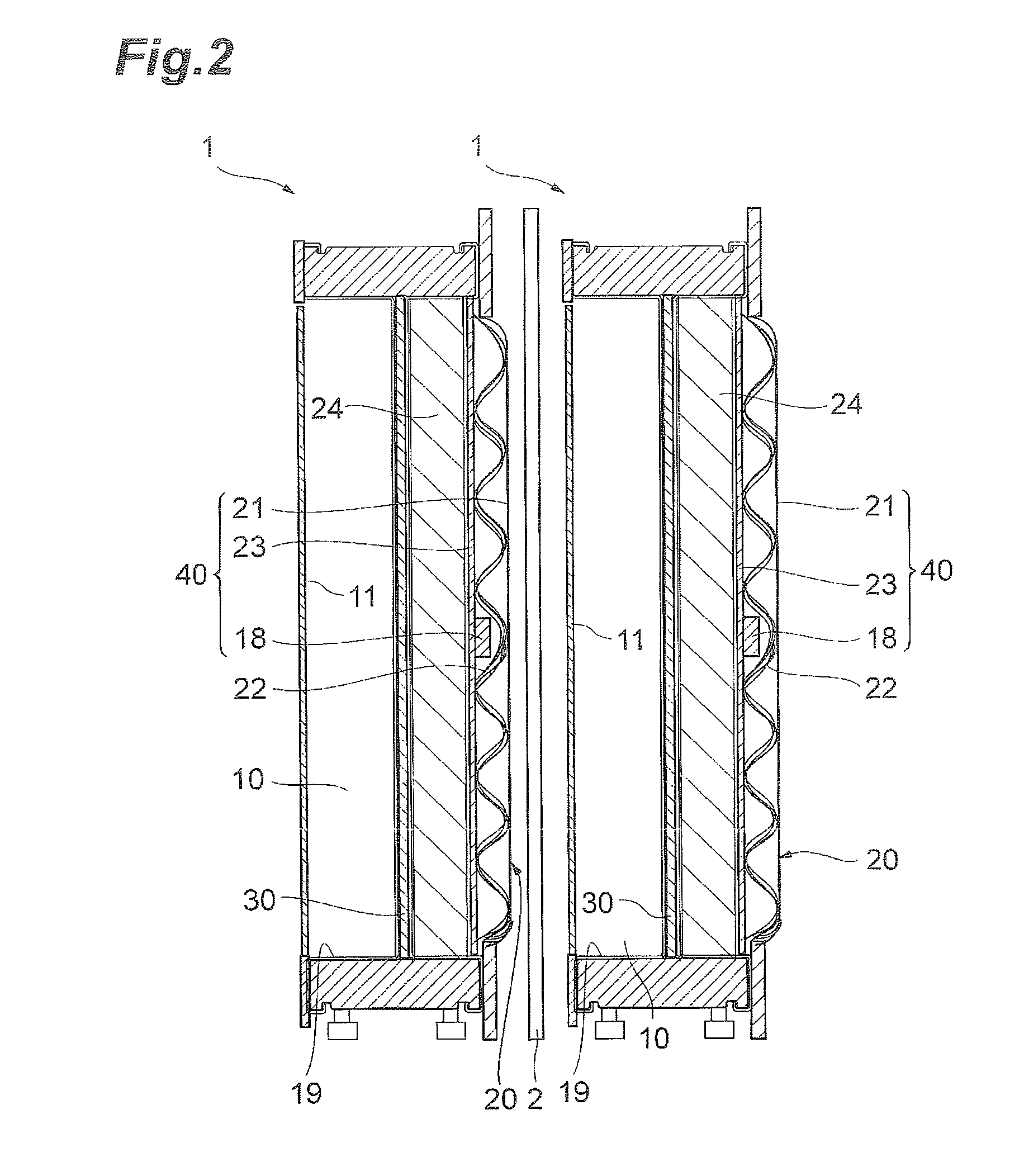
[0046]FIG. 1 is a cross-sectional view of an electrolysis cell 1 of a first embodiment of the invention. The electrolysis cell 1 is equipped with an anode chamber 10, a cathode chamber 20, a partition wall 30 installed between the anode chamber 10 and the cathode chamber 20, an anode 11 installed in the anode chamber 10, a cathode 21 installed in the cathode chamber 20, a reverse current absorbing body 18 having a substrate 18a and a reverse current absorbing layer 18b formed on the substrate 18a and installed in the cathode chamber. The anode 11 and the cathode 21 belonging to one electrolysis cell 1 are electrically connected. In other words, the electrolysis cell 1 is equipped with the following cathode structure. A cathode structure 40 is equipped with the cathode chamber 20, the cathode 21 installed in the cathode chamber 20, and the reverse current absorbing body 18 installed in the cathode chamber 20, and the reverse current absorbing body 18 has the substrate 18a and the rev...
second embodiment
[0137]A second embodiment is the same as the first embodiment except the following differences. Hereinafter, only the differences between the first embodiment and the second embodiment will be described, and the description on the common subject matters of both embodiments will be omitted. According to the second embodiment, it is possible to suppress the oxidation and degradation of the cathode in the same manner as the first embodiment.
[0138]FIG. 6 is a cross-sectional view of the electrolysis cell 1 according to the second embodiment. The electrolysis cell 1 according to the second embodiment is different from the electrolysis cell 1 according to the first embodiment in that a metal elastic body and a current collector are not equipped therein. The cathode chamber 20 equipped in the electrolysis cell 1 of the second embodiment has a support 24 disposed between a cathode 21 and a partition wall 30. The support 24 supports the cathode 21. The partition wall 30 is electrically conne...
example 1
[0143]The surface of nickel expanded metal (substrate) was plasma sprayed with nickel oxide powder, thereby coating the substrate with nickel oxide powder (reverse current absorbing layer). Nitrogen was used as the primary gas for the plasma spraying and hydrogen was used as the secondary gas. The electrolysis of salt to generate hydrogen was performed using the substrate coated with the reverse current absorbing layer as the cathode. The reverse current absorbing body of Example 1 was obtained through the reduction treatment by the electrolysis. Meanwhile, the conditions at the time of the electrolysis were as follows.
Current density: 4 kA / m2, electrolysis temperature: 90° C., and concentration of sodium hydroxide: 32% by weight.
[0144](Evaluation on Reverse Current Absorption)
[0145]The reverse current absorbing body was cut into a size of 3 cm×3 cm and fixed to a nickel rod coated with PTFE with nickel screws. A platinum plate was used as the counter electrode (anode).
[0146]The rev...
PUM
| Property | Measurement | Unit |
|---|---|---|
| diffraction angle 2θ | aaaaa | aaaaa |
| pore size | aaaaa | aaaaa |
| specific surface area | aaaaa | aaaaa |
Abstract
Description
Claims
Application Information
 - Generate Ideas
- Intellectual Property
- Life Sciences
- Materials
- Tech Scout
- Unparalleled Data Quality
- Higher Quality Content
- 60% Fewer Hallucinations
Browse by: Latest US Patents, China's latest patents, Technical Efficacy Thesaurus, Application Domain, Technology Topic, Popular Technical Reports.
© 2025 PatSnap. All rights reserved.Legal|Privacy policy|Modern Slavery Act Transparency Statement|Sitemap|About US| Contact US: help@patsnap.com


