
Panel-based solar receiver

a solar receiver and panel technology, applied in the field of solar energy facilities, can solve the problems of failure of pipes, insufficient amount for practically all applications, and high cost of sheet metal

Inactive Publication Date: 2015-01-22
ABENGOA SOLAR NEW TECH SA +1
View PDF6 Cites 14 Cited by
  • Summary
  • Abstract
  • Description
  • Claims
  • Application Information

AI Technical Summary

Benefits of technology

The patent text states that the invention has a back panel that is designed with external insulation to minimize loss of energy through convection and radiation. Additionally, the surface of the panel is smooth and free of major discontinuities, which makes it easier to apply a uniform layer of paint or absorbent coating. These technical effects help improve the performance of the invention.

Problems solved by technology

This amount is insufficient for practically all applications wherein said energy must be converted into work.
The drawback is that its cost is higher than its flat equivalent (for example sheet metal), owing to the greater complexity of manufacturing it.
In both cases, the joints must reduce the size of the areas not cooled by the working fluid as far as possible, owing to the fact that these points form hot spots, the high temperature of which could lead to failure in the pipes.
Both solutions increase turbulence and tangential flow speed, especially near the pipe wall.

Method used


Image

  • Panel-based solar receiver
  • Panel-based solar receiver
  • Panel-based solar receiver

Examples


Embodiment Construction

[0017]The present invention describes a panel-based receiver for a thermal solar tower power plant, which may be used for both cavity facilities and external facilities.

[0018]The receiver comprises:

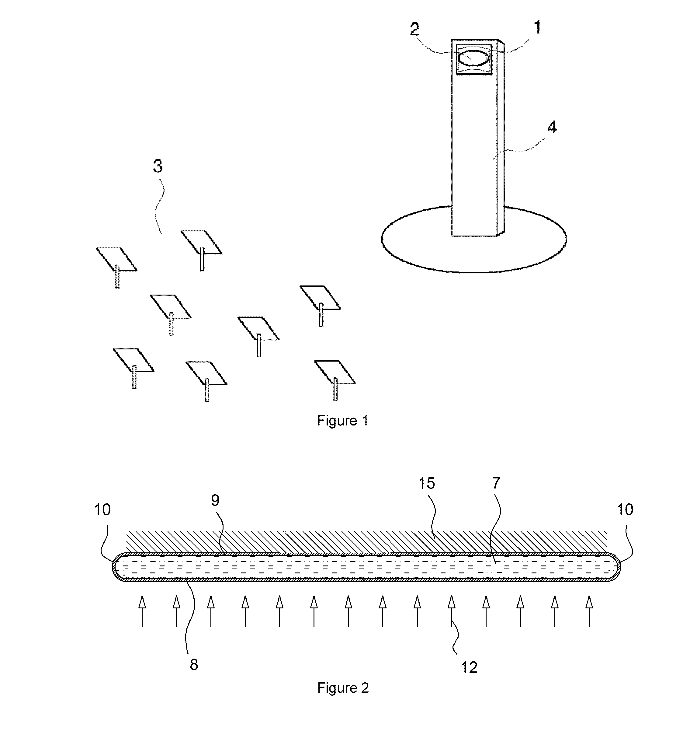
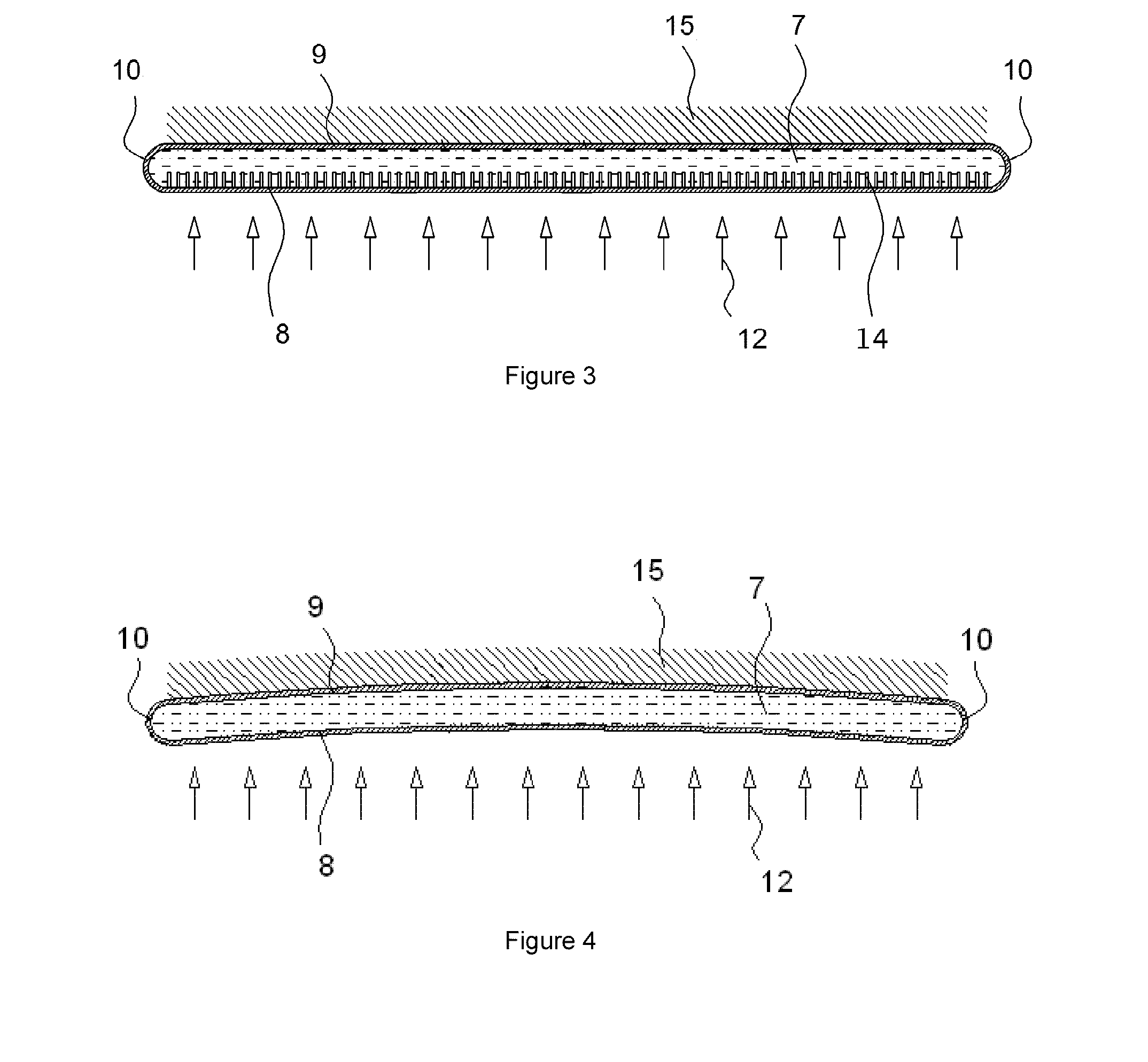
[0019]a front panel, the external surface of which receives solar radiation from the field of heliostats,

[0020]a back panel, which is usually equipped with external insulation that reduces loss via convection and radiation into the environment,

[0021]sealing elements between the panels, arranged at the lateral ends of both

[0022]at least one intake collector, located in the upper part of the panels, where the fluid enters the receiver and

[0023]at least one evacuation collector, located in the lower part of the panels, where the fluid leaves the receiver,[0024]wherein the front panel, back panel and the two sealing elements form the central receiver body, which constitutes a passage for the heat transfer fluid to travel through.

[0025]In the invention, it is envisaged that the heat transfer f...


PUM


Abstract

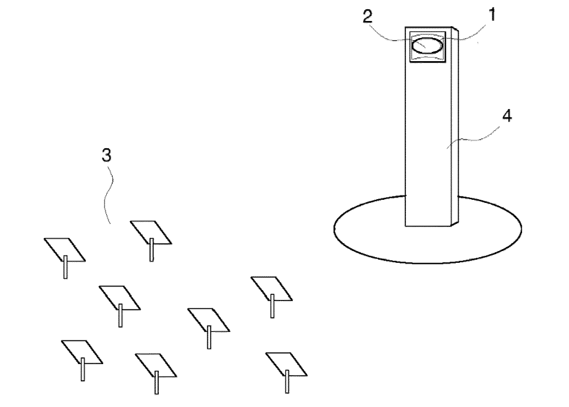
The invention relates to a panel-based solar receiver for a thermal solar tower power plant (4), which comprises: a front panel (8), the external surface of which receives solar radiation (2) from the field of heliostats (3), a back panel (9), sealing elements (10) between the panels (8, 9), arranged at the lateral ends of both, an intake collector (5), located in the upper part of the panels (8,9), where the heat transfer fluid enters the receiver (1) and an evacuation collector (6), located in the lower part of the panels (8, 9), where the heat transfer fluid leaves the receiver (1); wherein the front panel (8), back panel (9) and the two sealing elements (10) form the receiver body (16), which constitutes a passage for the heat transfer fluid (7) to travel through. Each solar tower can contain one or several panel-based receivers (1) and be arranged in series or in parallel, with the same or a different fluid (7) circulating there through.

Description

APPLICATION FIELD OF THE INVENTION[0001]The present invention belongs to the solar energy facilities sector and more specifically, pertains to receiver systems for thermal solar tower power plants.BACKGROUND OF THE INVENTION[0002]The amount of solar energy per time and area unit received on earth, when the Earth is at an average distance from the sun, on a normal surface thereof, is approximately 1 KW / m2. This amount is insufficient for practically all applications wherein said energy must be converted into work. The solution is to use systems or facilities that optically concentrate on a focal point, in order to reach greater flow densities and therefore, higher temperatures.[0003]Since time began, humans have tried to take advantage of concentration using mirrors to reach high temperatures. It is believed that Archimedes (287-212 BCE) wrote a book entitled, “On burning mirrors”, no copies of which have survived and which forms part of the myth-reality surrounding the destruction o...

Claims


Application Information

Patent Timeline
Patent Type & Authority Applications(United States)
IPC IPC(8): F24J2/07F24S10/50F24S10/60F24S20/20F24S23/70
CPCF24J2/07F24J2002/1076F24J2002/075F24J2/207F24J2002/4601Y02E10/44F28F3/048Y02E10/41F24J2/20F24J2/51F24S10/20F24S10/50F24S10/505F24S20/20F24S40/50F24S50/00F24S80/30F24S80/60F24S2023/87F24S2080/03F24S10/60F24S2020/23Y02E10/40
Inventor LLORENTE FOLCH, PAULANAVIO GILABERTE, RA LSERRANO GALLAR, LUCIACASTRO DE BENITO, ANDRESVILLARRICA VINAS, JORGECOCA VALDES, PABLO
Owner ABENGOA SOLAR NEW TECH SA
Learn More