Multi-rotation encoder

a multi-rotation encoder and encoder technology, applied in the field of multi-rotation encoders, can solve the problems of poor maintainability, cost increase, and difficulty in improving durability, and achieve the effect of higher accuracy

Inactive Publication Date: 2015-01-15
MITSUBISHI ELECTRIC CORP
View PDF0 Cites 11 Cited by
  • Summary
  • Abstract
  • Description
  • Claims
  • Application Information

AI Technical Summary

Benefits of technology

[0028]With the battery-less multi-rotation encoder in one aspect of the present invention, the controller in the signal processing circuit is adapted to set states of the respective detection coils and store the states in the memory, wherein the states are set, using both the positive and negative voltage pulses which are outputted from the L detection coils and based on no voltage pulse being generated therefrom, to be High or Low and further to maintain High or Low when no voltage pulse is being generated therefrom. Further, the number of rotations is detected based on this stored state, which enables counting the number of rotations without losing count thereof, even when the rotational shaft is reversely rotated halfway through rotations. Therefore, assuming that the number of magnetic poles is N in the magnet included in the rotation detection mechanism, it is possible to detect the rotational angle of the rotational shaft within about 1 / (LN) rotation, which enables detecting the number of rotations of the rotational shaft with higher accuracy than those with conventional structures.

Problems solved by technology

However, the latter encoders are required to electrically hold the resultant number of rotations, even in the event of shutdowns of external power supplies.
Therefore, they have the problem of poor maintainability, since there is a need for replacement of the backup battery at regular time intervals.
On the other hand, the former types of encoders have the advantage of being capable of holding the number of rotations regardless of the presence or absence of an external power supply, since they count and hold the number of rotations in mechanical manners, but they involves complicated structures, thereby inducing the problems of cost increases and difficulty of improving the durability.

Method used


Image

  • Multi-rotation encoder
  • Multi-rotation encoder
  • Multi-rotation encoder

Examples


first embodiment

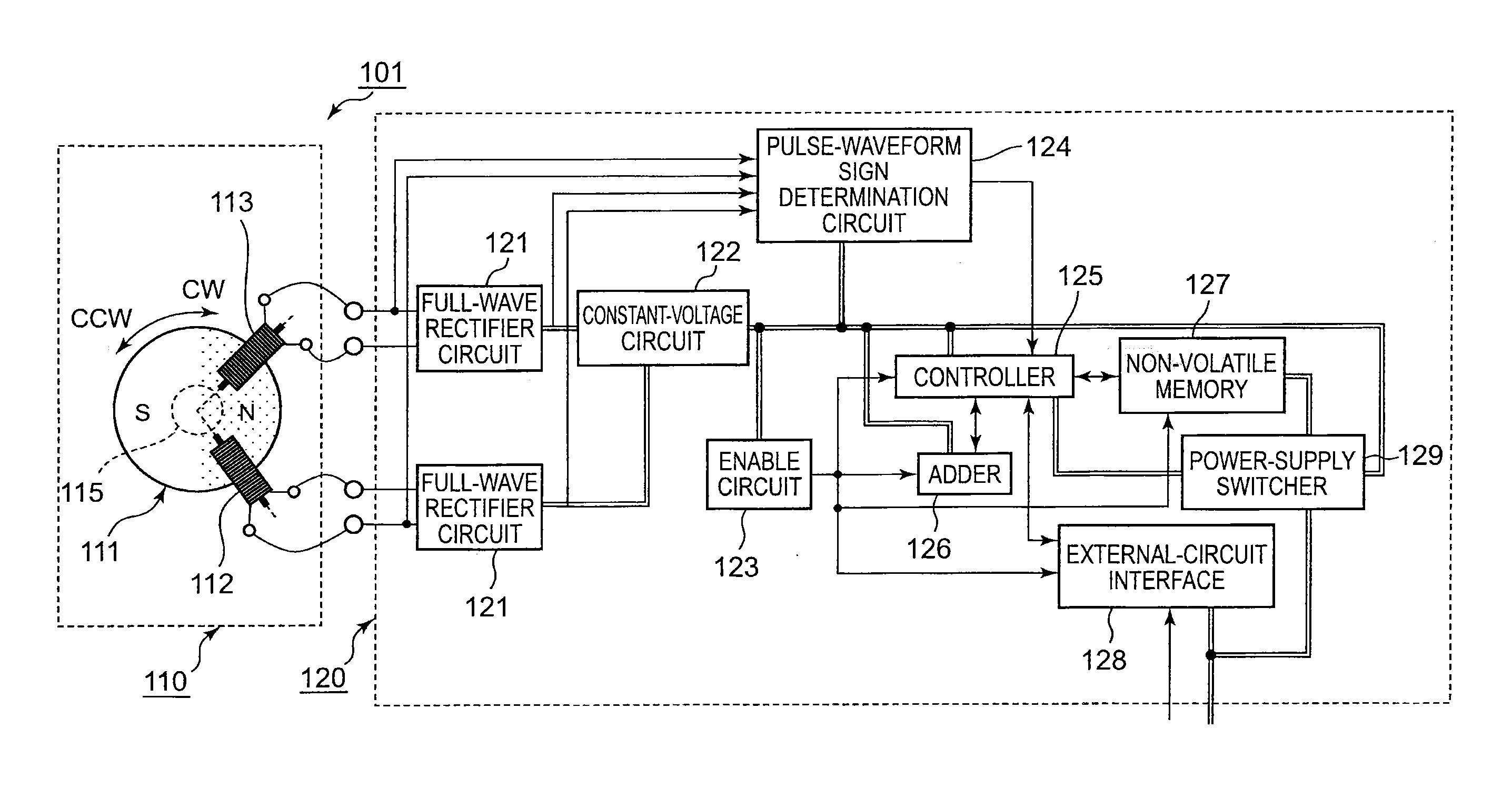
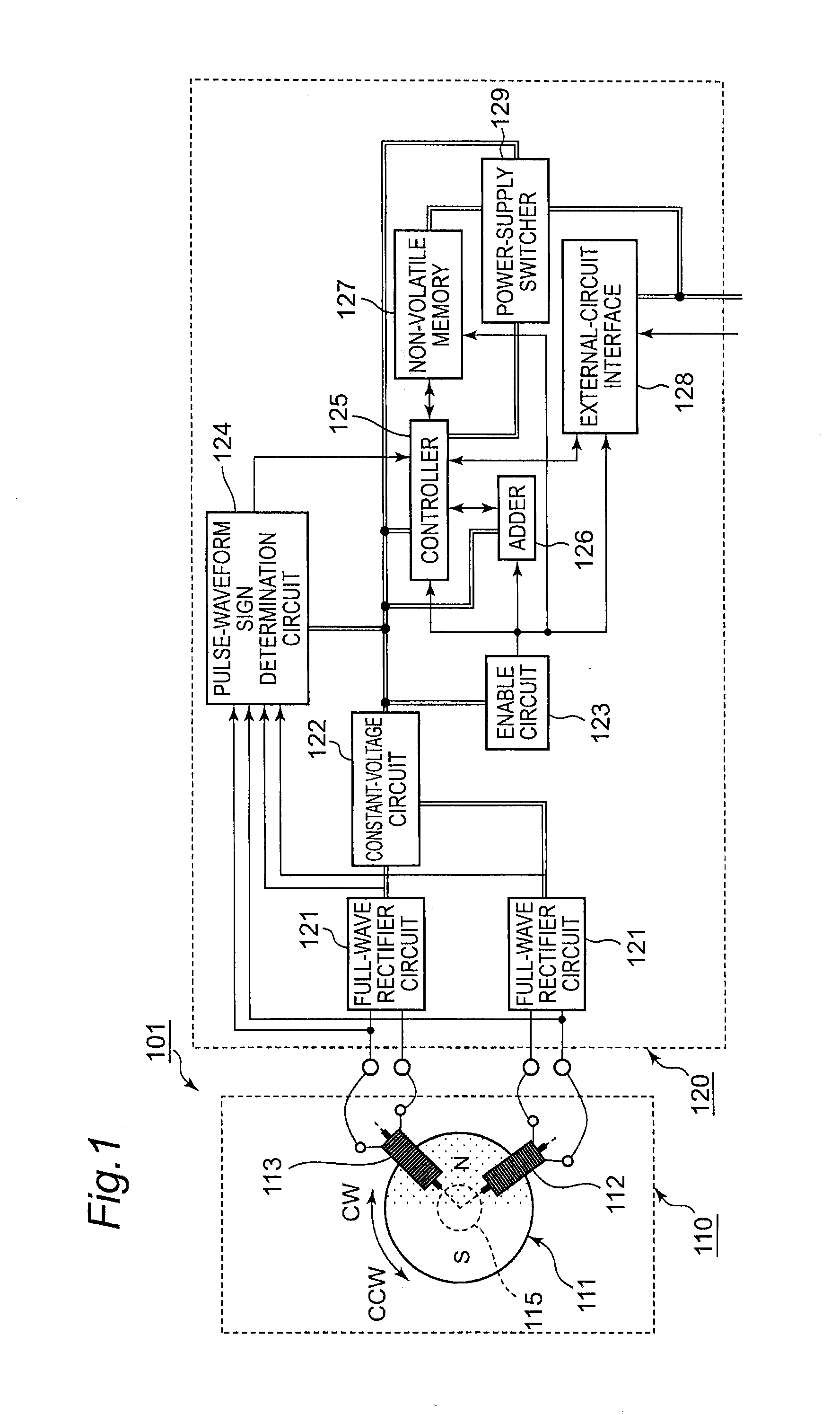
[0047]FIG. 1 illustrates the structure of a battery-less multi-rotation encoder 101 according to a first embodiment of the present invention. The battery-less multi-rotation encoder 101 according to the present embodiment is a multi-rotation encoder adapted to detect and hold the rotational direction and the number of rotations of a rotational shaft, without being supplied with electric power from the outside. The battery-less multi-rotation encoder 101 generally includes a rotation detection mechanism 110 and a signal processing circuit 120 which is electrically connected to the rotation detection mechanism 110.

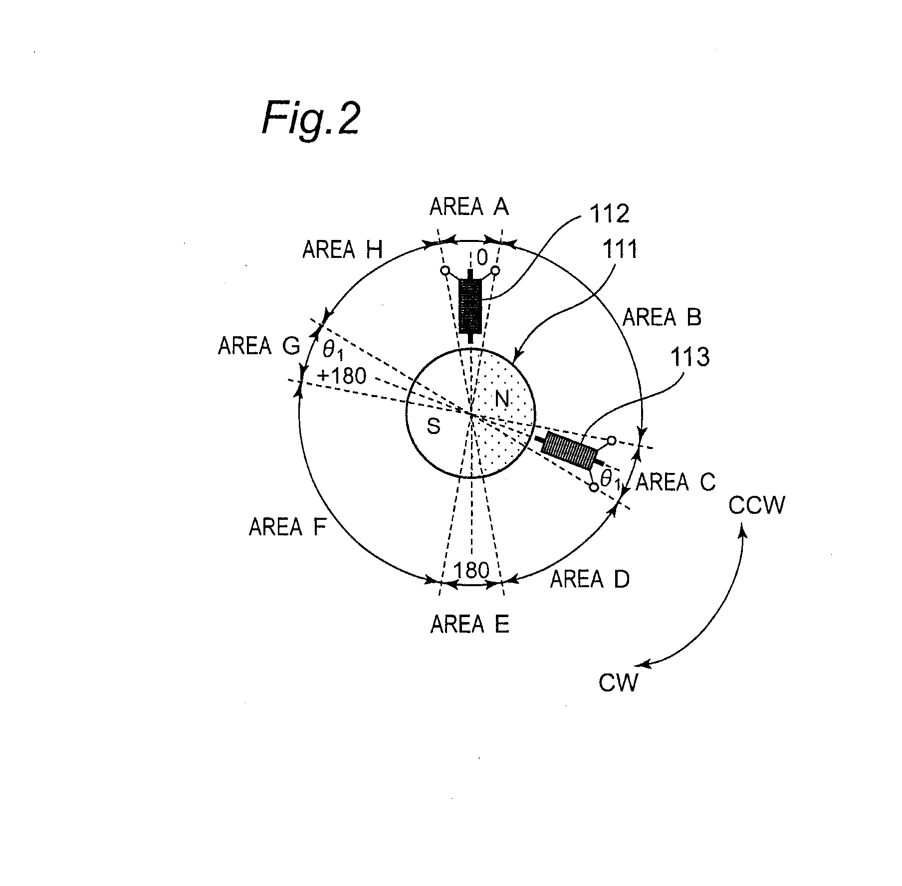
[0048]As illustrated in FIG. 2, the rotation detection mechanism 110 is a mechanism which includes a magnet 111, and detection coils 112 and 113 and is adapted to detect rotations of a rotational shaft 115. Further, the rotational shaft 115 corresponds to the output shaft (the rotational shaft) of a motor and the like, for example, but is not limited thereto and corresponds ...

second embodiment

[0072]With reference to FIG. 8, there will be described a battery-less multi-rotation encoder 102 according to a second embodiment of the present invention.

[0073]The battery-less multi-rotation encoder 102 according to the present embodiment also includes the rotation detection mechanism 110, and a signal processing circuit which is electrically connected to the rotation detection mechanism 110, similarly to the aforementioned battery-less multi-rotation encoder 101. The battery-less multi-rotation encoder 102 according to the present embodiment is different from the aforementioned battery-less multi-rotation encoder 101 in that it includes a signal processing circuit 131 instead of the signal processing circuit 120. Further, the signal processing circuit 131 is different from the signal processing circuit 120 in that the non-volatile memory 127 is placed outside the signal processing circuit. The other structures in the signal processing circuit 131 are the same as those in the sig...

third embodiment

[0075]With reference to FIG. 9, there will be described a battery-less multi-rotation encoder 103 according to a third embodiment of the present invention.

[0076]The battery-less multi-rotation encoder 103 according to the present embodiment also includes the rotation detection mechanism 110, and a signal processing circuit which is electrically connected to the rotation detection mechanism 110, similarly to the aforementioned battery-less multi-rotation encoder 101. The battery-less multi-rotation encoder 103 according to the present embodiment is different from the aforementioned battery-less multi-rotation encoder 101 in that it includes a signal processing circuit 132 instead of the signal processing circuit 120. Further, the signal processing circuit 132 is different from the signal processing circuit 120 in that full-wave rectifier circuits 121 and the constant-voltage circuit 122 are placed between the rotation detection mechanism 110 and the signal processing circuit 132, out...


PUM


Abstract

A battery-less multi-rotation encoder including detection coils with the Barkhausen effect includes a rotation detection mechanism and a signal processing circuit. The detection coils generate voltage pulses with different positive and negative signs, and transmit them to the signal processing circuit, and the signal processing circuit includes a controller and an adder. The controller can set states of the detection coils to be High or Low and to maintain them at High or Low, based on the positive and negative signs of the respective voltage pulses and no voltage pulse being generated therefrom. The controller is configured to store the states of the respective detection coils in a memory. The adder can update a number of rotations according to the changes in the states of the respective detection coils. The signal processing circuit can determine the rotational angle of a rotational shaft within about 1 / 4 rotation unit.

Description

TECHNICAL FIELD[0001]The present invention relates to multi-rotation encoders capable of detecting and then holding the direction of rotations of a rotating member in a motor and the like, and the number of rotations thereof, without being supplied with electric power from the outside.BACKGROUND ART[0002]In general, a rotary encoder for detecting the rotational angle of a motor rotational shaft, for example, is constituted by a rotational disk which is coupled to the motor rotational shaft and is provided with optical or magnetic patterns thereon, and a detection device for reading the aforementioned optical or magnetic patterns. As rotary encoders of this type, there have been known those of increment types which are adapted to integrate pulse signals detected by the detection device for detecting the rotational angle of the rotational shaft. Further, there have been known those of absolute types which are adapted to detect an absolute angle of the rotational disk from a plurality ...

Claims


Application Information

Patent Timeline
Patent Type & Authority Applications(United States)
IPC IPC(8): G01B7/30G01D5/12
CPCG01D5/12G01B7/30G01D5/2013G01D5/00G01D5/244G01D5/245
Inventor INOUE, JINMUSHA, TAKESHINISHIZAWA, HIROSHINAKAJIMA, HAJIMETAKEUCHI, RYOSUKEITO, TATSUYAHIRAI, TAKASHINAGATA, HIROSHI
Owner MITSUBISHI ELECTRIC CORP
Why Eureka
Try Eureka