
Self-Cleaning Toilet Assembly and System

a self-cleaning, toilet technology, applied in the field of flushing toilets, can solve the problems of poor performance in bulk removal, rapid rise in water level, and manual cleaning of the bowl, and achieve the effect of excellent cleaning ability

Active Publication Date: 2015-01-15
AS AMERICA
View PDF7 Cites 44 Cited by
  • Summary
  • Abstract
  • Description
  • Claims
  • Application Information

AI Technical Summary

Benefits of technology

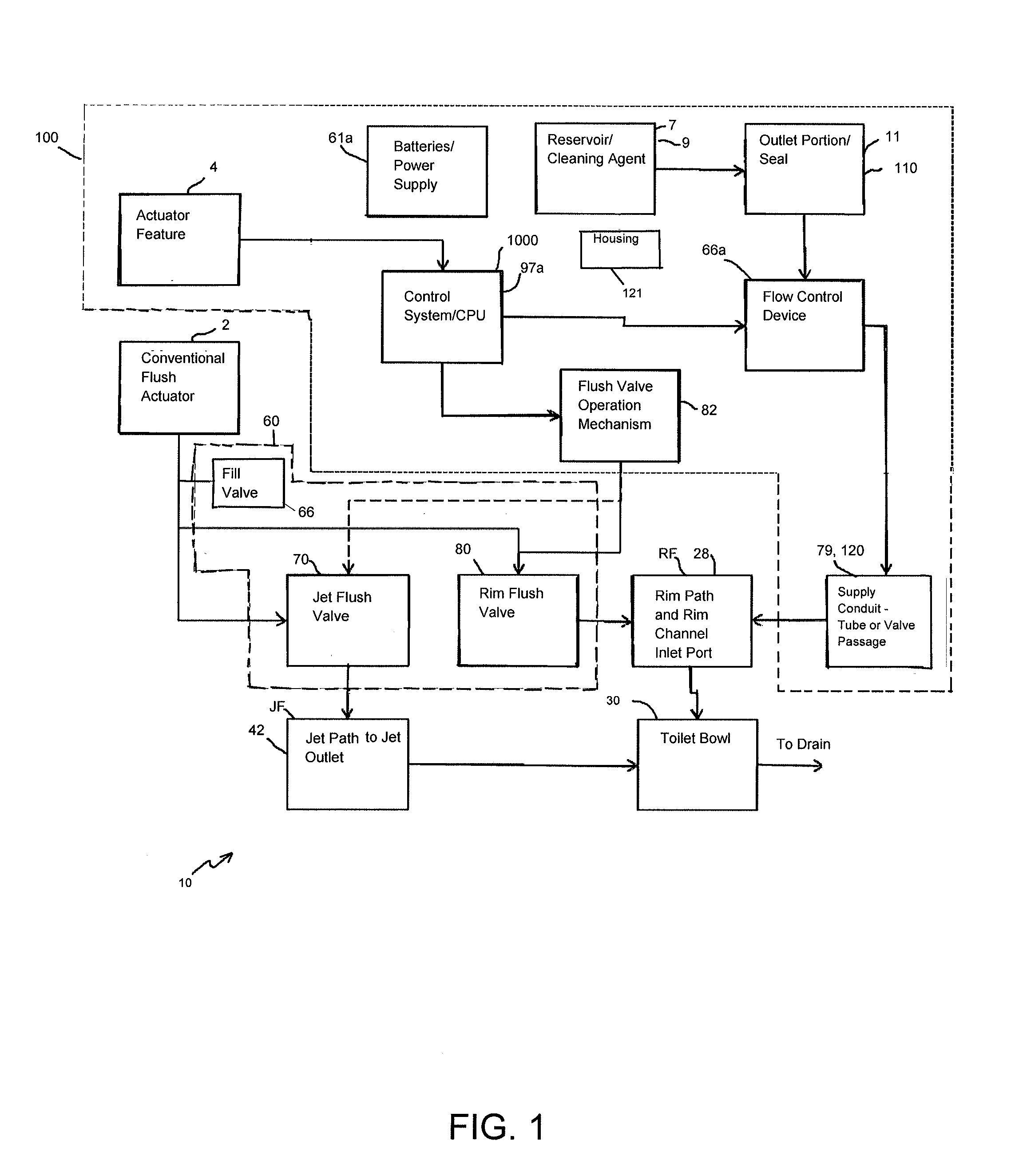
The invention is a toilet assembly with a toilet and a cleaning system. The toilet can be a regular toilet or one designed to isolate the rim path. The cleaning system is a self-cleaning toilet that users can initiate when they need to. Unlike other toilets with cleaning systems, this invention doesn't automatically flush when you use it. It aims to provide excellent cleaning while minimizing exposure to cleaning agents.

Problems solved by technology

This causes a rapid rise in water level and the excess water spills over the weir of the trapway, carrying liquid and solid waste along with it.
Siphonic toilets, due to the requirement that most of the air be removed from the down leg of the trapway in order to initiate a siphon, tend to have smaller trapways which can result in clogging.
Wash-down toilets with their small water spots therefore frequently require manual cleaning of the bowl after use.
Non-jetted bowls typically have adequate to good performance with respect to cleansing of the bowl and exchange of the pre-flush water, but are relatively poor in performance in terms of bulk removal.
The feed of water to the trapway is inefficient and turbulent, which makes it more difficult to sufficiently fill the down leg of the trapway and initiate a strong siphon.
Without the smaller size, bends, and constrictions, a strong siphon would not be achieved.
Unfortunately, the smaller size, bends, and constrictions result in poor performance in terms of bulk waste removal and frequent clogging, conditions that are extremely dissatisfying to end users.
Although rim jetted bowls are generally superior to non-jetted, the long pathway that the water must travel through the rim to the jet opening dissipates and wastes much of the available energy.
In addition to the types of toilets and their cleaning capability, there is pressure to use less water, making the cleaning function more difficult.
The 1.6 gallons / flush toilets currently described in the patent literature and available commercially lose the ability to consistently siphon when pushed to these lower levels of water consumption.
Thus, manufacturers are being and will continue to be forced to reduce trapway diameters and sacrifice performance without development of improved technology and toilet designs.
While all such improvements have been made, the continuous introduction of cleaning fluid that works in various prior art systems to introduce cleaning agent with repeated flushing or that allows cleaning agent to sit in the bowl has not been well received by consumers, either due to complex external systems which are hard to operate or fill and / or as a result of the overuse of cleaning agents in the flush water which can prove harmful in high concentrations to pets and children if ingested.
Further, overuse of cleaning agents over time can cause damage to the internal parts within the toilet bowl such as rubber seals and the like.
Finally, some of such systems are not aesthetically pleasing and have many external parts that are within plain site of the user.

Method used


Image

  • Self-Cleaning Toilet Assembly and System
  • Self-Cleaning Toilet Assembly and System
  • Self-Cleaning Toilet Assembly and System

Examples


embodiment 400

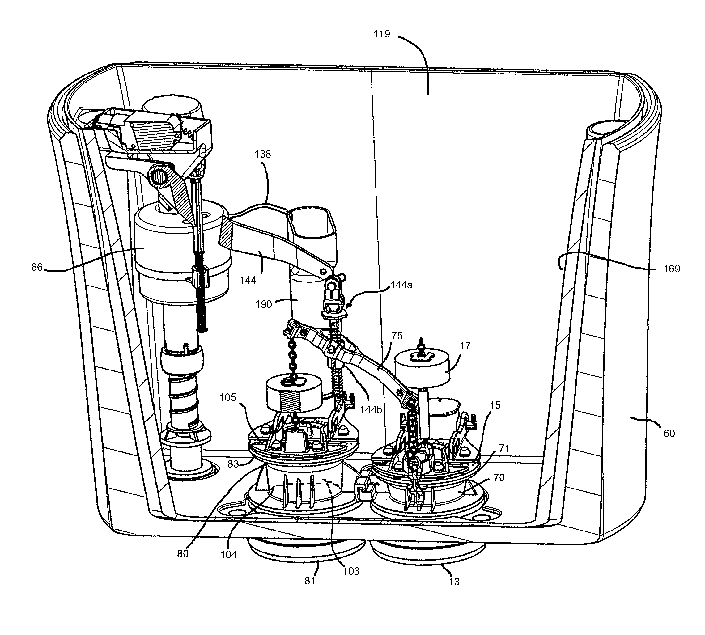
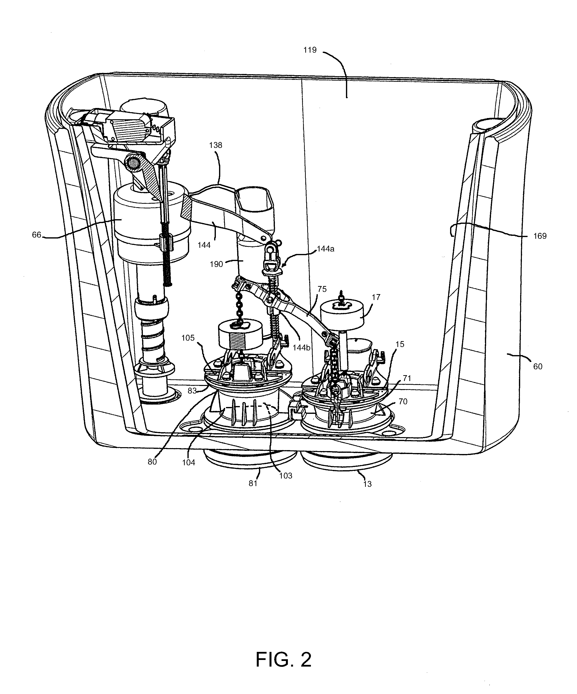
[0166]The flapper lift mechanism is positioned on or around a valve body of the rim flush valve and the lift mechanism upon mechanical actuation by a gear motor when actuated by the control system, can lift and manually operate the rim flush valve during the clean cycle and / or a flush cycle. In a conventional flush cycle, the rim and jet flush valves are preferably operated by a flush actuator as described herein. The flush handle may be part of the flush valve operation mechanism 82 as described for example in this embodiment 10 as well as embodiments 500 and 1900 to open the rim flush valve. Or the flush valve operation mechanism 82 may be a form of mechanized flapper lift mechanism with a lift rod as in the embodiment 400. Various flush operation mechanisms may operate by a gear motor activatable by the control system for operating the flush valve. A flow control device for metering of solution, using a gear pump and / or gear motor, a peristaltic pump, a rotating device and the li...

embodiment 10

[0184]The sump area 40 of the bowl preferably has a jet trap 41 defined by the interior surface 39 of the bowl 30. The jet trap 41 has an inlet end 46 and an outlet end 50. The inlet end 46 of the jet trap receives fluid from the jet outlet port 42 and the interior area 37 of the bowl 30 and the outlet end 50 of the jet trap 41 receives that flow which enters into the inlet 49 to the trapway 44. The jet trap has a seal depth. The seal depth may be varied along with the jet paths and the measurement of the depth and all such variations may be readily incorporated into and operable in the embodiment 10. Such variations are described in detail in International Publication No. 2014 / 078461, incorporated herein in relevant part to describe variations in jet path and seal depth options for this particular toilet assembly.

[0185]To maintain a siphonic flush toilet assembly such as assembly 10 in a primed state, the initial step is to provide a toilet bowl assembly having the features as desc...

embodiment 100

[0261]The toilet bowl 30 may be of a variety of shapes and configurations as with toilet 10 in embodiment 100 described herein, and may have a variety of toilet seat lids and / or lid hinge assemblies. As such lids and are optional they are not shown in the drawings, and any suitable lid known or to be developed may be used with the invention.

[0262]As shown in FIG. 13, the shelf 27 can extend around almost the entire interior surface. It terminates to induce a vortex flow effect for cleaning. A rim shelf design can also accommodate multiple rim shelves and multiple rim inlets as described in co-pending U.S. Publication No. 2013 / 0219605 A1, incorporated herein by reference in relevant part in terms of describing rimless features. A similar design as shown in U.K. Patent Application No. GB 2 431 937 A or any future variations of such designs, wherein the bowl is formed without the traditional hollow rim and water is directed around a contoured interior surface of the bowl in an upper pe...


PUM


Abstract

Toilet assemblies having various embodiments of a cleaning system are described herein which include a toilet assembly and a cleaning system. The toilet assembly has a toilet bowl, a tank, a flush valve, and a rim in fluid communication with the bowl through a rim flow path from an outlet of the flush valve to at least one rim outlet port. The flush valve is configured to operate in a flush actuation mode wherein the flush valve is able to provide flush water flow sufficient for the toilet assembly to initiate a flush siphon or provide a wash down flush and to operate in a cleaning actuation mode wherein the flush valve is only partially opened to allow for introduction of a cleaning agent and flush water mixture to the bowl that is insufficient to initiate a siphon but sufficient for cleaning the bowl. The cleaning system includes a reservoir for a liquid cleaning agent, a housing for the reservoir, a supply conduit for receiving fluid from within the reservoir and delivering it to a flush valve, a flow control device capable of controlling flow of cleaning agent and a control system activatable by an actuator feature to initiate a clean cycle by operating the flow control device to deliver a dose of cleaning agent to one or more rim outlets, and operating the flush valve in cleaning actuation mode to introduce flush water to carry the dose of cleaning agent through the at least one rim outlet port into the toilet bowl at a flow rate insufficient to initiate a siphon but sufficient for cleaning the bowl.

Description

CROSS-REFERENCE TO RELATED APPLICATIONS[0001]This application claims the benefit under 35 U.S.C. §119(e) to U.S. Provisional Patent Application No. 61 / 980,514, filed Apr. 16, 2014, U.S. Provisional Patent Application No. 61 / 950,038, filed Mar. 8, 2014, U.S. Provisional Patent Application No. 61 / 908,038, filed Nov. 22, 2013, U.S. Provisional Patent Application No. 61 / 881,948, filed Sep. 24, 2013, and U.S. Provisional Patent Application No. 61 / 846,427, filed Jul. 15, 2013, each entitled “Self-Cleaning Toilet Assembly and System,” the disclosures of which are hereby incorporated by reference in their entirety.BACKGROUND OF THE INVENTION[0002]1. Field of the Invention[0003]The field of the invention includes flush toilets, and more particularly certain gravity-powered wash down or siphonic flush toilets having a cleaning system with a cleaning cycle.[0004]2. Description of Related Art[0005]There are a wide variety of types of toilets and toilet assemblies having toilet bowls, including ...

Claims


Application Information

Patent Timeline
Patent Type & Authority Applications(United States)
IPC IPC(8): E03D9/02E03D9/00
CPCE03D9/02E03D2009/028E03D9/002E03D9/035E03D2201/40E03D9/037
Inventor BUCHER, CHRISTOPHEGROVER, DAVIDBARNDT, RONALDSEGGIO, FRANKMCHALE, JAMESCICENAS, CHRISO'KELLY, MATTHEW
Owner AS AMERICA
Learn More