Ventilation device for clean room applications

a technology for ventilation devices and clean rooms, applied in ventilation systems, lighting and heating apparatuses, heating types, etc., can solve the problems of large space requirements for different functional units, complex design of ventilation systems, and relatively high installation and startup costs, so as to eliminate or minimize the above-mentioned inadequacies of conventional ventilation systems. , the effect of simple installation, maintenance and startup

Active Publication Date: 2015-01-08
DALDROP & DR ING HUBER
View PDF27 Cites 12 Cited by
  • Summary
  • Abstract
  • Description
  • Claims
  • Application Information

AI Technical Summary

Benefits of technology

[0009]Considering the foregoing, it is the object of the present invention to eliminate or minimize the aforementioned inadequacies of conventional ventilation systems for clean rooms and provide the most compact possible, integrated ventilation device that is suitable for clean room applications. In particular, it is an object of the present invention to provid...

Problems solved by technology

The design of such a ventilation system is complex in that it requires considerable space for the different functional units, the duct network, the sensors and the control system.
In addition, the expenses for installation and startup are relatively high due to the numerous connections between connectors that need to be provided, the relatively complex preliminary wiring and preliminary specification of parameters.
Also, the maintenance and servicing of such a distributed system is difficult.
During operation, problems can occur when adapting the functional units to each other and when regu...

Method used


Image

  • Ventilation device for clean room applications
  • Ventilation device for clean room applications
  • Ventilation device for clean room applications

Examples


Embodiment Construction

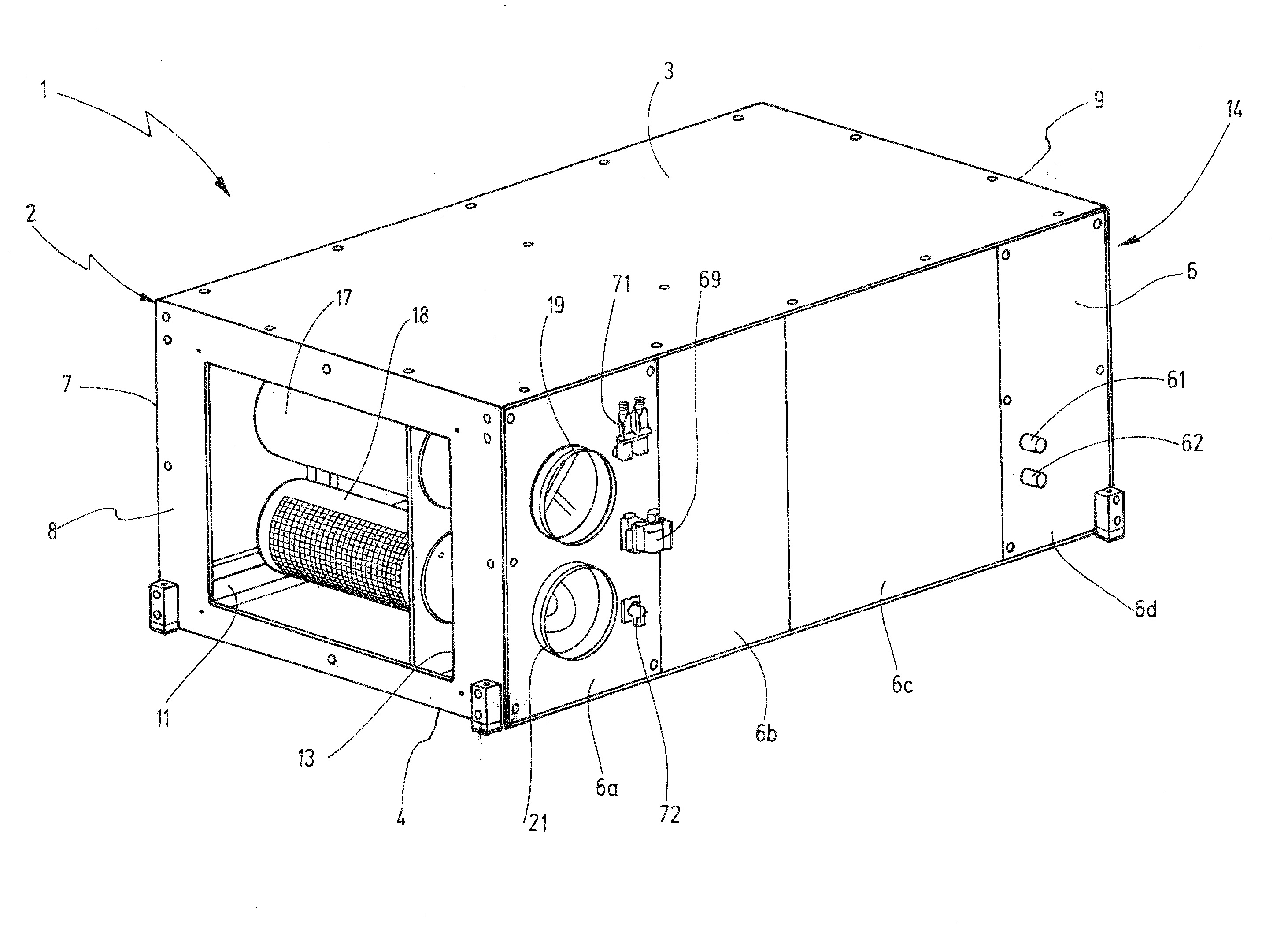
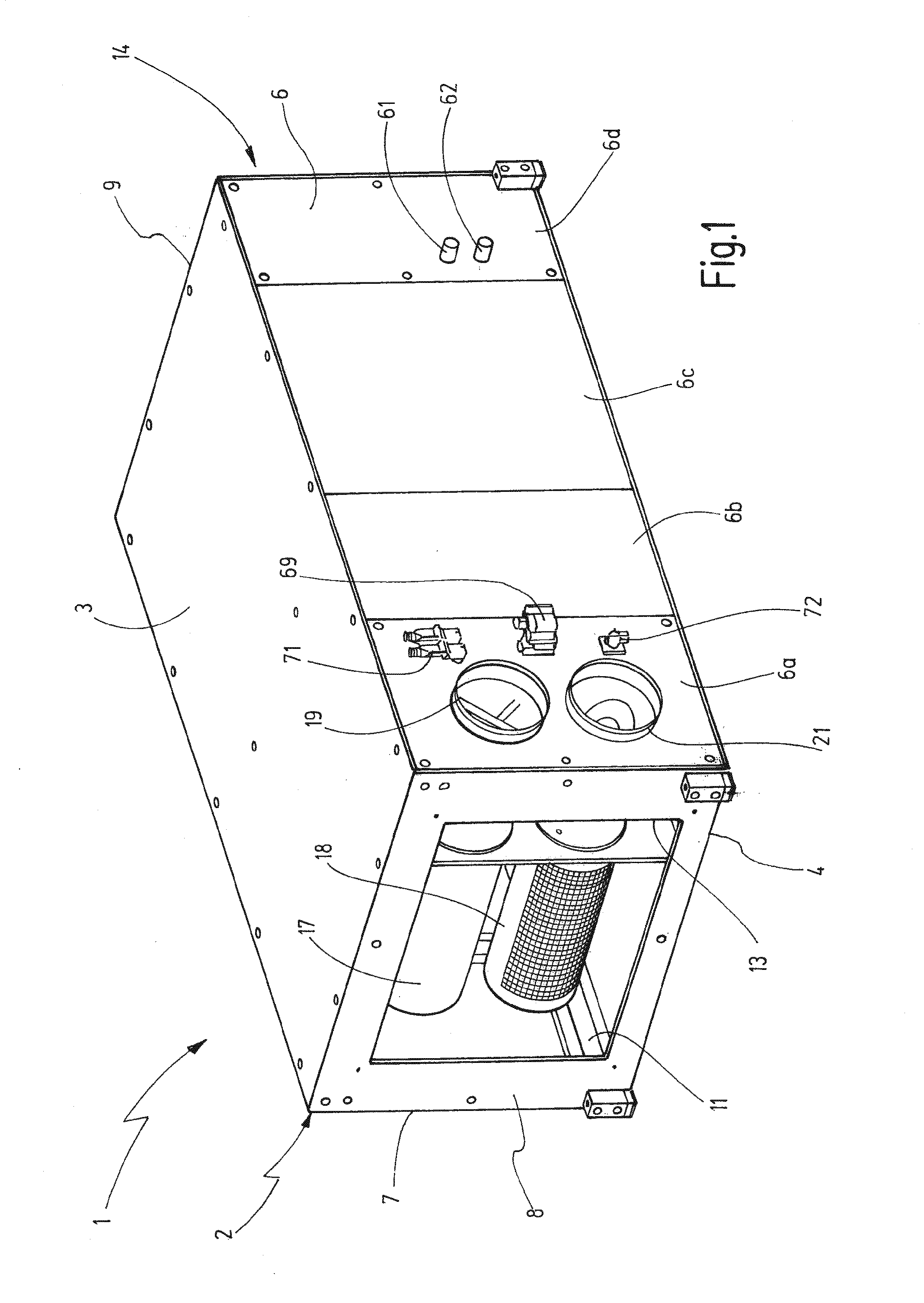
[0037]Referring now more particularly to FIG. 1 of the drawings, there is shown an illustrated ventilation device for supplying air to and extracting air from a room, in particular a clean room in accordance, with a preferred embodiment of the invention. The ventilation device 1 comprises a housing 2 having the shape of an elongated parallel-piped having an upper side 3, an underside 4, two longitudinal sides 6, 7, and two narrow sides 8, 9. However, it is understood that the ventilation device need not necessarily be used in the depicted horizontal position but may also be used in a vertical position, e.g., with the narrow side directed upward.

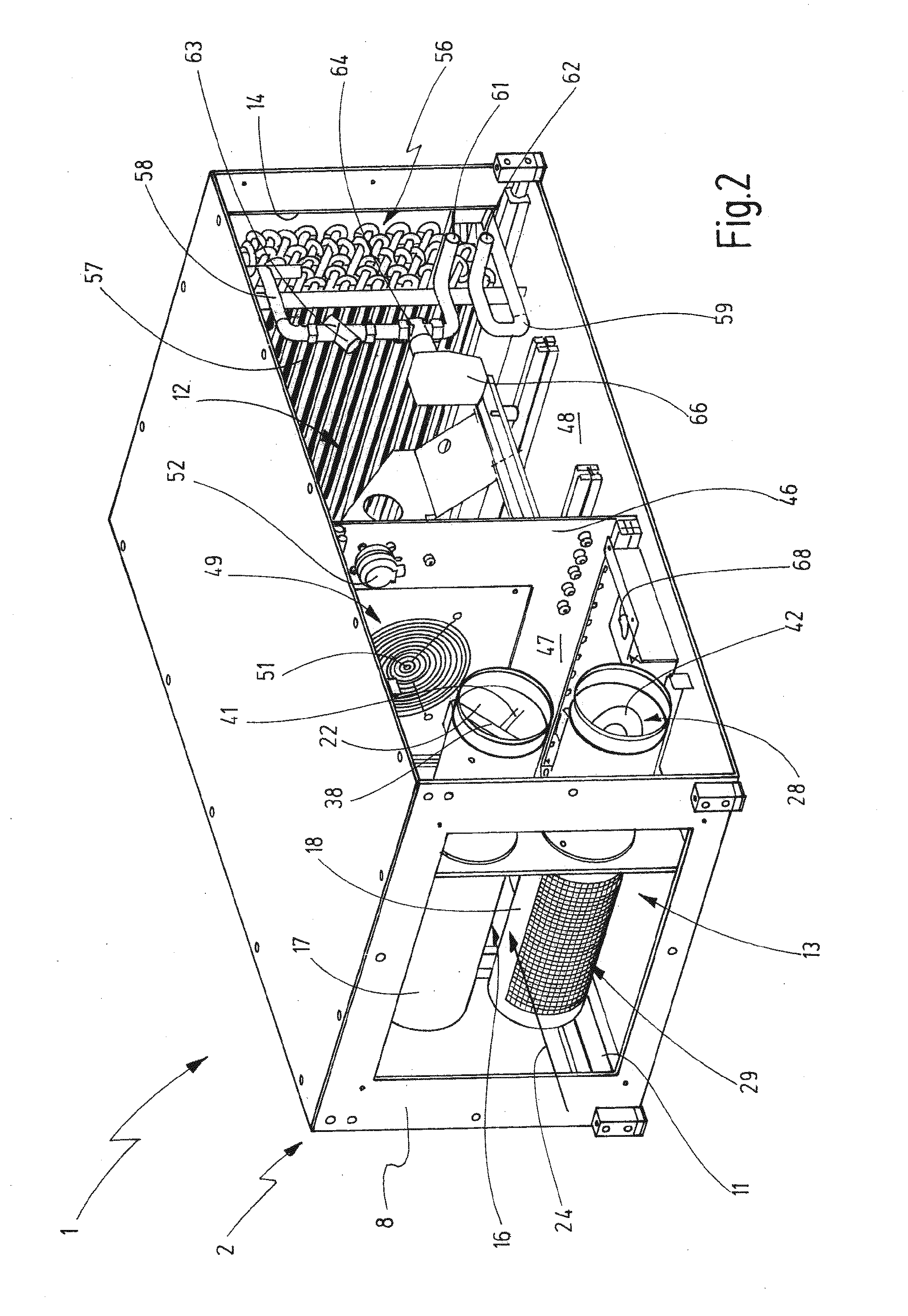
[0038]The housing sides 2 to 9 are represented by the housing covers that are mounted to a bearing frame structure 11 fastened with screws so as to create a seal. The frame structure 11 that is constructed in this case with a durable but light-weight design of extruded aluminum profiles, is indicated in FIGS. 1 and 2.

[0039]The housing covers ...


PUM


Abstract

A ventilation device for supplying air to a clean room having a passage duct (16) with a waste air inlet (13) for receiving waste air form the room and a supply air outlet (14) for discharging supply air (34) to the room. A speed controllable rotatable fan (49) is provided in the passage duct (16) for conveying air from a suction chamber (47) coupled to the waste air inlet (13) to a pressure chamber (48) coupled to the supply air outlet (14). An outside air duct (22) is provided for receiving outside air (27) which is emitted into the passage duct (16), and an exhaust air duct (28) is provided for receiving a part of the waste air (32) extracted from the room for exhaust to the outside. First and second air flow regulators (36, 37) are provided in the respective air ducts (22, 28), and a control unit (68) is provided for controlling operation of the air flow regulators (36, 37) and the rotational speed of the fan (49).

Description

FIELD OF THE INVENTION[0001]The present invention relates to a ventilation device for supplying and extracting air from a room, in particular a clean room.BACKGROUND OF THE INVENTION[0002]Clean rooms of this type, to which the present invention relates in particular, are used predominantly in the fields of pharmaceutics, biotechnology and microelectronics. Operations or production processes must be performed in clean rooms in closed spaces under controlled conditions. Depending on the application and requirements related thereto, various parameters such as, e.g., air temperature, air humidity, room pressure, particle and germ count can be influenced or controlled in a targeted manner in such clean rooms. Depending on the required degree of purity, excess pressure or negative pressure in the clean room, different clean room classes have been known and standardized.[0003]In order to maintain one or several of the aforementioned parameters in a clean room, special ventilation systems a...

Claims


Application Information

Patent Timeline
IPC IPC(8): F24F3/16F24F11/00F24F7/007F24F1/0038F24F3/167F24F1/0071
CPCF24F3/16F24F2011/0041F24F11/0012F24F7/007F24F11/0001F24F1/0018F24F11/30F24F2110/10F24F2110/60F24F2110/40F24F11/77F24F1/0035Y02B30/70F24F3/167F24F1/0038F24F1/0071F24F11/63
Inventor OSWALD, JOSEF
Owner DALDROP & DR ING HUBER
Why Eureka
Try Eureka