Sterilization System And Method With Compression and Expansion
a technology of sterilization system and expansion chamber, applied in the direction of disinfection, water installation, construction, etc., can solve the problem of condensation on surfaces including the inside of the lumen
- Summary
- Abstract
- Description
- Claims
- Application Information
AI Technical Summary
Benefits of technology
Problems solved by technology
Method used
Image
Examples
second embodiment
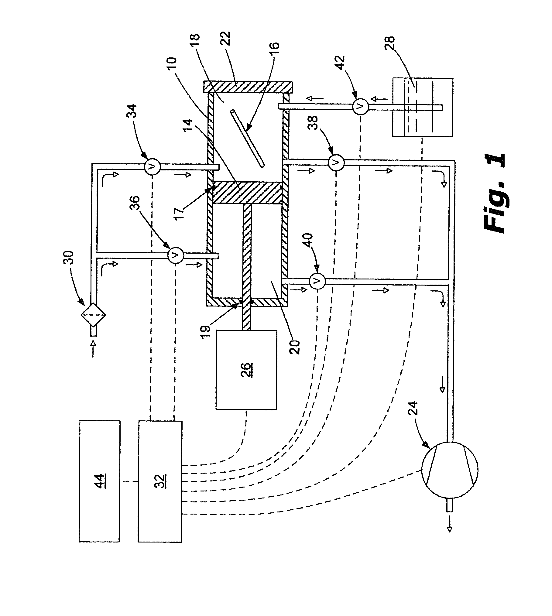
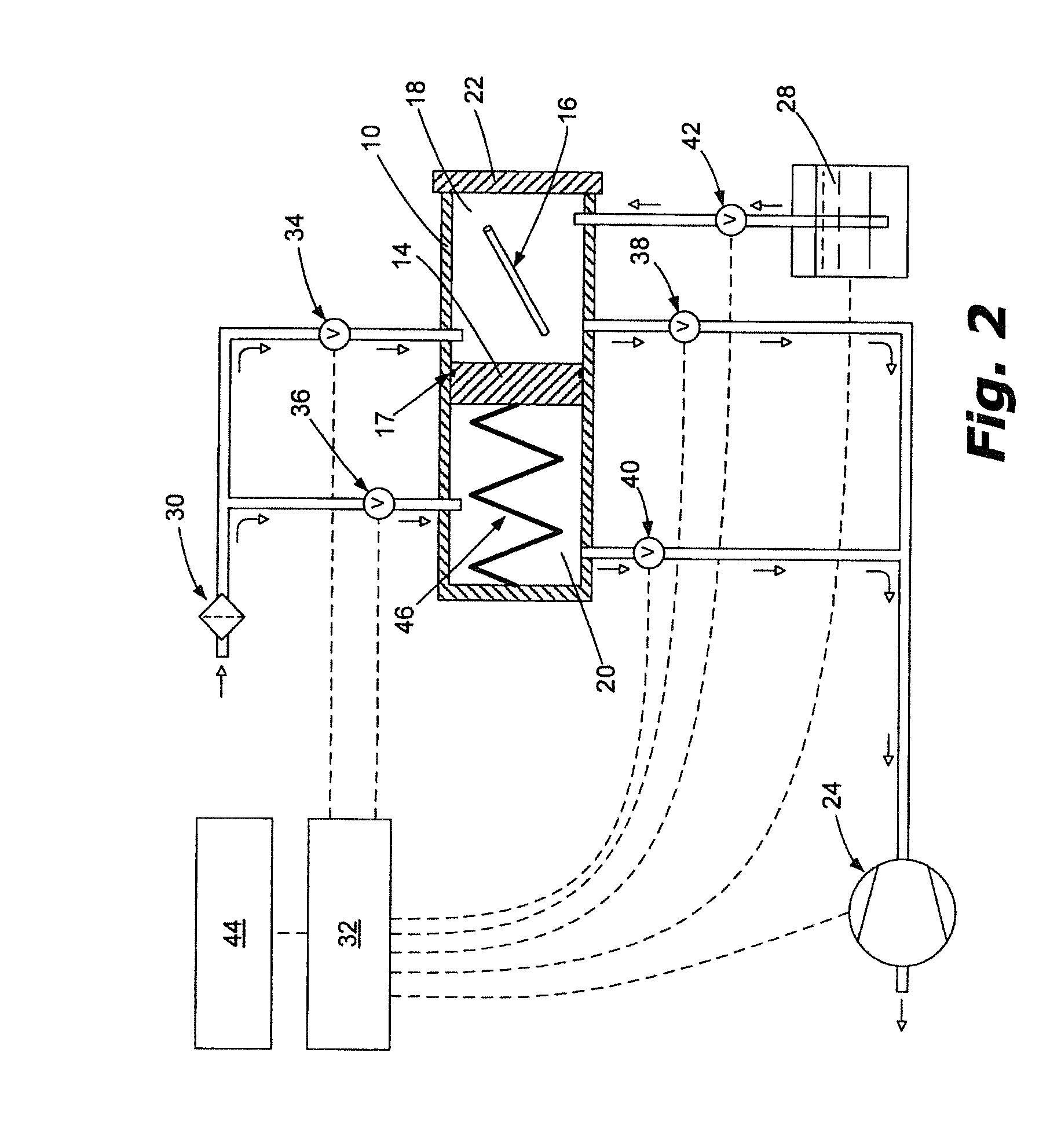
[0040]FIG. 2 is a schematic diagram of a variable volume sterilizer system. In this embodiment, as in the embodiment shown in FIG. 1, the sterilization chamber 10 is divided into two portions: a first area 18 in which item(s) to be sterilized 16 are placed and into which sterilant is admitted; and the second area 20. Area 18 and area 20 are separated by a movable boundary 14 that is sealed with respect to the chamber walls, but slidable such that the relative sizes of chamber areas 18 and 20 can be altered as part of the sterilization process via controlled movement of the movable boundary 14. More specifically, the first area 18 and second area 20 are separated by the movable boundary 14, so that when the second volume 20 is increased, the first volume 18 consequently decreases, and vice versa. One advantage of using a second area 20 within the sterilization chamber 10 is that this area may also be evacuated. When the second area 20 is at a pressure near to that of the first area 1...
third embodiment
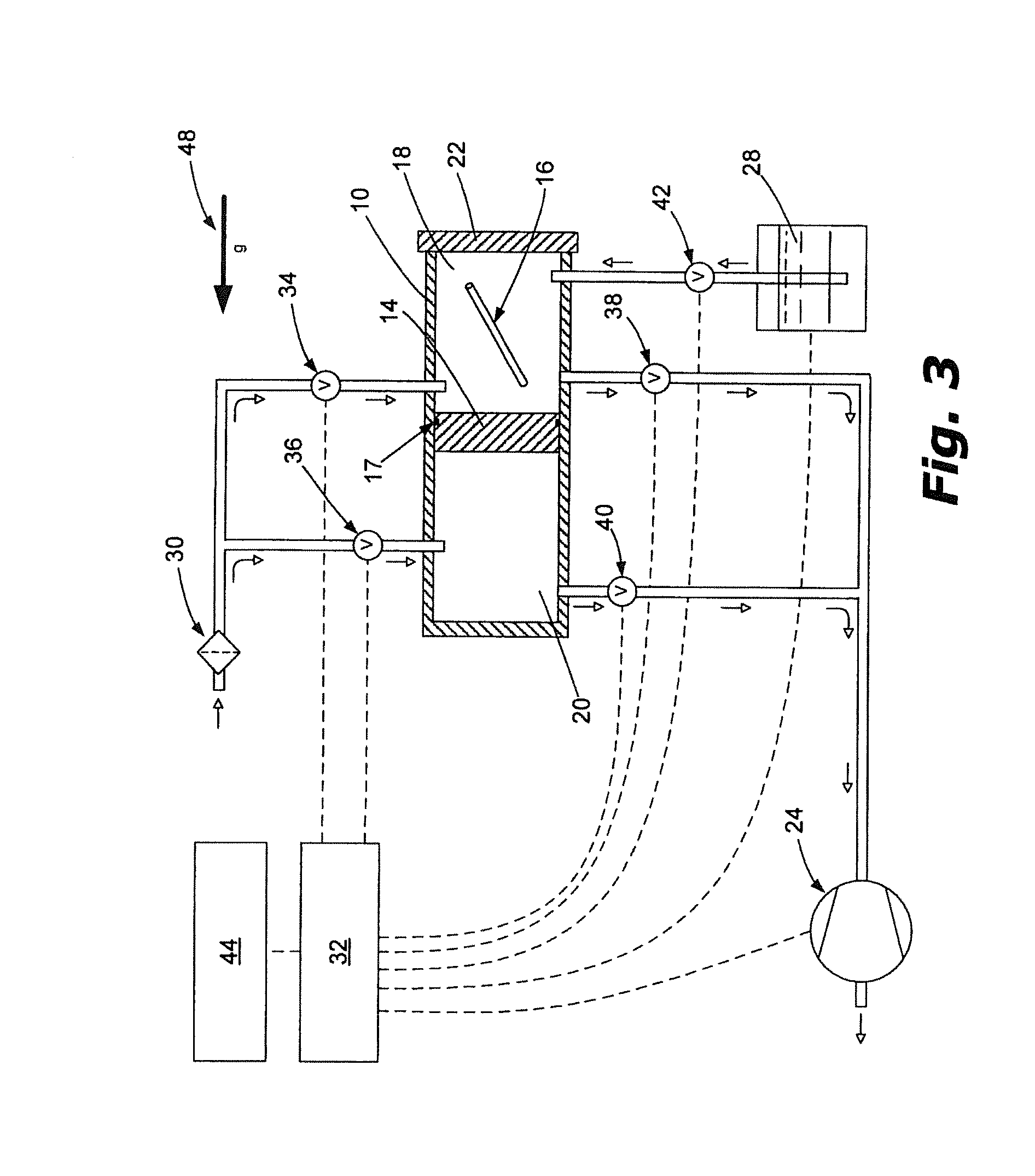
[0043]FIG. 3 is a schematic diagram of a variable volume sterilizer system similar to the embodiment of FIG. 2. In this embodiment, the spring 46 has been removed and the movable boundary 14 is moved by using the controlled actuation of inlet valve 36 and / or the outlet valve 40. Any pressure differential between areas 18 and 20 will cause the movable boundary 14 to move. When the pressure in area 20 is lower than the pressure in area 18, the boundary will move to reduce the volume of area 20 and expand the volume of area 18 in an effort to equalize the pressures of the two areas. Likewise, when the pressure in area 20 is greater than the pressure in area 18, the movable boundary 14 will move in the opposite direction. Arrow 48 in FIG. 3 is present to suggest that gravity can also be employed to expand the size of area 18 except when the pressure in area 20 is sufficiently higher than the pressure in area 18 to resist the force of gravity.
fourth embodiment
[0044]FIG. 4 is a schematic diagram of a variable volume sterilizer system. In this embodiment valves 36 and 40 of the previously described embodiments have been eliminated such that actuator 26 exclusively controls the position of the movable boundary 14.
PUM
| Property | Measurement | Unit |
|---|---|---|
| pressure | aaaaa | aaaaa |
| pressure | aaaaa | aaaaa |
| pressure | aaaaa | aaaaa |
Abstract
Description
Claims
Application Information
 - R&D
- Intellectual Property
- Life Sciences
- Materials
- Tech Scout
- Unparalleled Data Quality
- Higher Quality Content
- 60% Fewer Hallucinations
Browse by: Latest US Patents, China's latest patents, Technical Efficacy Thesaurus, Application Domain, Technology Topic, Popular Technical Reports.
© 2025 PatSnap. All rights reserved.Legal|Privacy policy|Modern Slavery Act Transparency Statement|Sitemap|About US| Contact US: help@patsnap.com


