Image forming apparatus
- Summary
- Abstract
- Description
- Claims
- Application Information
AI Technical Summary
Benefits of technology
Problems solved by technology
Method used
Image
Examples
first embodiment
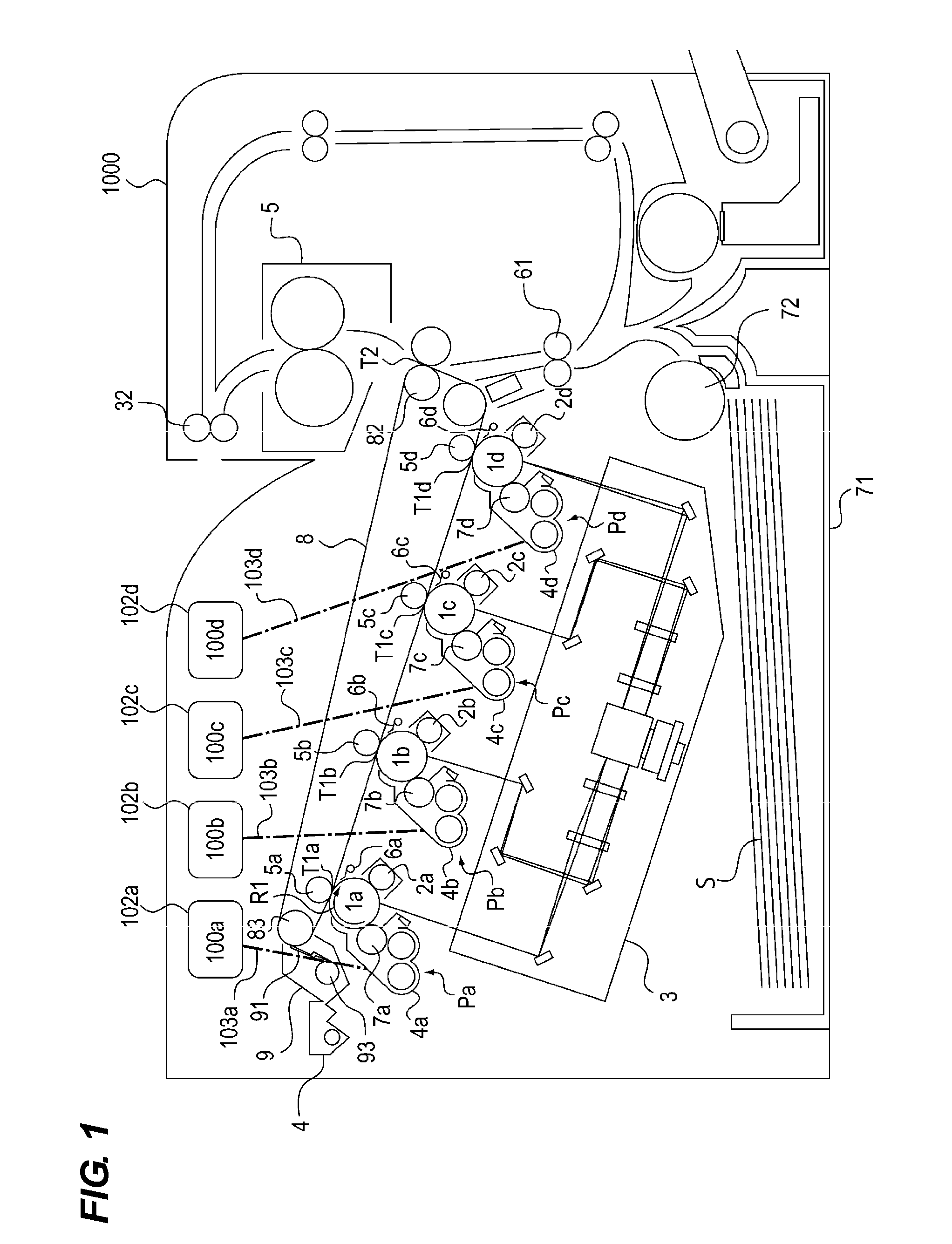
[0032]Hereinafter, exemplary embodiments of the present invention will be described in detail with reference to the accompanying drawings. The image forming apparatus of the present invention may also be implemented in another embodiment in which a part or the entire of the configuration of the embodiment is replaced with alternative configuration, as long as it includes a toner bottle and a toner replenishing portion.
[0033]Therefore, four image bearing members contacting an intermediate transfer member are illustrated in drawings, but it is not limited thereto, and the present embodiment also may be implemented in an image forming apparatuses having three or less or five or more image bearing members contacting the intermediate transfer member. Further, although only major portions related to toner replenishment are described in the present embodiment, the present invention may be implemented in many uses such as printers, various types of printers, copying machines, facsimile mach...
second embodiment
[0091] An image forming apparatus 2200 according to the present invention will be described. FIG. 8 is a cross-sectional view of a color image forming apparatus using an electrophotographic system. The image forming apparatus 2200 is a so-called intermediate transfer tandem type image forming apparatus, in which four color forming portions are arranged in parallel on an intermediate transfer belt 2007. The intermediate transfer tandem method is a configuration that makes a main stream recently in view of the fact that it can deal with high productivity and various media carriers. Moreover, the direction perpendicular to ground in FIG. 8 is the front to back direction.
[0092] Recording materials S are stored in a form loaded on a storage tray 2010, and is dispatched on image forming timing by a feeding roller 2061 using a friction separation method. The recording material S sent out by the feeding roller 2061 passes through a conveying path and is conveyed on registration roller 2062....
third embodiment
[0138]Hereinafter, a third embodiment will be described, while components of the third embodiment having the same configuration as the second embodiment are denoted by the same reference numerals and will be described below. As illustrated in FIG. 13, based on the installation information, the gear portion 2020a rotates by the driving input from the motor 2080 at a predetermined time, and the driving is transmitted to the sliding gear 2044, thereby the worm gear 2045, the slider 2030 and the claw 2030a start to move, and the pump portion 2020b is expanded and compressed.
[0139]Herein, toner near the pump portion 2020b flows along with the expanding and compressing operation of the pump portion 2020b, and the pressed-solidified toner (tapped toner) by vibration during transport is loosened to reduce the bulk density thereof. Due to the flowing of the toner to the discharge port 2021a near the pump portion 2020b, the bulk density of the toner near the discharge port 2021a is reduced.
[0...
PUM
 Abstract
Description
Claims
Application Information
 - R&D
- Intellectual Property
- Life Sciences
- Materials
- Tech Scout
- Unparalleled Data Quality
- Higher Quality Content
- 60% Fewer Hallucinations
Browse by: Latest US Patents, China's latest patents, Technical Efficacy Thesaurus, Application Domain, Technology Topic, Popular Technical Reports.
© 2025 PatSnap. All rights reserved.Legal|Privacy policy|Modern Slavery Act Transparency Statement|Sitemap|About US| Contact US: help@patsnap.com


